Component Test Procedures 2-5
1. Remove power from the drive. Refer to Removing Power from the
Drive on page 3-3.
2. Disconnect all motor leads from the drive.
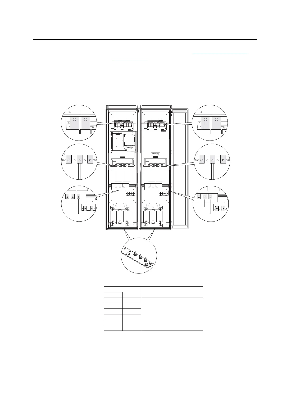
3. Conduct forward and reverse biased diode tests on the Rectifying
Modules (if present).
Figure 2.1 Measurement Points for Forward and Reverse Diode Tests
DANGER DANGER
DC BUS CONDUCTORS AND CAPACITORS
OPERATE AT HIGH VOLTAGE. REMOVE POWER
AND WAIT 5 MINUTES BEFORE SERVICING
DANGER DANGER
DC BUS CONDUCTORS AND CAPACITORS
OPERATE AT HIGH VOLTAGE. REMOVE POWER
AND WAIT 5 MINUTES BEFORE SERVICING
Cat No.
1234567890-*
FIELD INSTALLED OPTIONS:FIELD INSTALLED OPTIONS:
DC- DC+ DC- DC+
1L1
1L2
1L3
2L1
2L2
2L3
1U/T1
1V/T2
1W/T3
2U/T1
2V/T2
2W/T3
Power Structure #1 Power Structure #2
Table 2.A Forward Biased Diode Tests on Rectifying Module for Power Structure #1
Meter Leads
Nominal meter reading-+
DC+/R+
(1)
(1)
If the drive does not contain the brake chopper option, the DC+/R+
terminal will be labeled DC+.
1L1
Meter should beep once and value
should gradually rise to about 0.5V
DC+/R+ 1L2
DC+/R+ 1L3
1L1 DC-
1L2 DC-
1L3 DC-

 Loading...


