8 Rockwell Automation Publication 750-IN105D-EN-P - June 2018
PowerFlex 750-Series Service Cart and DC Precharge Module Lift
Remove the Power Module
Follow these sections to remove a power module from a control cabinet.
Prepare the Equipment for Service
This section prepares you to service LCL filter modules, power modules, or DC precharge module.
Follow these steps to prepare the equipment for removal.
1. Remove power and de-energize the cabinet.
See PowerFlex 755TM Power and Filter Module Storage Hardware Instructions, publication
750-IN106.
2. Open the door.
3. Remove all applicable safety guards.
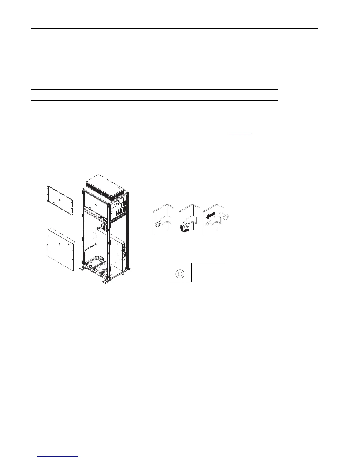
a. Refer to this image for configurations that do not contain a DC precharge module.
The mounting screws for safety guards can remain in the cabinet. The safety guard slides past the head of a loosened screw.
IMPORTANT The LCL filter or power module must be removed to remove a DC precharge module.
Example of safety guard flanges:
M5.5
T25
4.8 N•m (23 lb•in)
The 800 mm (31.5 in.) cabinet configuration is shown and is typical of other sizes.

 Loading...


