EasyManua.ls Logo

Allen-Bradley PowerFlex 750 Series User Manual

Allen-Bradley PowerFlex 750 Series
50 pages
To Next Page IconTo Next Page
To Previous Page IconTo Previous Page
Page #11 background image
Rockwell Automation Publication 750-UM003D-EN-P - March 2017 11
Safety Concepts Chapter 1
ATEX System
The overall system includes an ATEX certified motor that is installed in a
potentially explosive atmosphere. The motor is equipped with a thermal sensor
that is connected to the ATEX option input. Do not install the drive in a
potentially explosive atmosphere. See Figure 1
.
Figure 1 - Basic ATEX Application
The ATEX option module monitors the thermal sensor in the motor. When
the thermal sensor reaches its trip point, the drive initiates a Safe Torque Off
function and removes torque-producing power from the motor. The ATEX
safety function has a safety integration level (SIL) capability limit of 1
according to IEC 61508.
ATEX Function
The PowerFlex 750-Series ATEX option module can be configured to support
ATEX certified motors that are equipped with either a thermostat or a PTC-
type thermal sensor.
WARNING: Risk of Explosion.
Do not install the PowerFlex 750-Series drive or PowerFlex 755T drive products
in a potentially explosive atmosphere.
A drive that is installed in a potentially explosive atmosphere can cause an
explosion.
PowerFlex 750-Series Drive or PowerFlex 755T drive products (750-Series drive shown)
Power to the Motor
Thermal Sensor Input to the Drive
Potentially Explosive Atmosphere
ATEX Certified Motor
ATTENTION: Risk of electric shock. If a motor insulation fault occurs, high
voltage can be present at the ATEX terminal block and wiring. Be sure that all
drive covers are installed when power is applied to the drive.

Table of Contents

Other manuals for Allen-Bradley PowerFlex 750 Series

Question and Answer IconNeed help?

Do you have a question about the Allen-Bradley PowerFlex 750 Series and is the answer not in the manual?

Allen-Bradley PowerFlex 750 Series Specifications

General IconGeneral
CategoryController
SeriesPowerFlex 750 Series
DimensionsVaries by model
WeightVaries by model
Output Voltage Range0V to Input Voltage
Output Frequency Range0 to 400 Hz
Control MethodVector Control
Communication ProtocolsEtherNet/IP, DeviceNet, ControlNet
Enclosure TypesNEMA 1, NEMA 12, NEMA 4X, IP20
SafetySafe Torque Off (STO)
Ambient Operating Temperature0 to 40 °C (32 to 104 °F)
Storage Temperature-40°C to 70°C (-40°F to 158°F)
Relative Humidity5% to 95% (non-condensing)
AltitudeUp to 1000m (3280 ft) without derating

Summary

Important User Information

Safety Warnings and Precautions

Summarizes warnings, cautions, and important notes for safe operation and installation.

Chapter 1 Safety Concepts

ATEX Directive 2014/34/EU

Explains the ATEX directive and its compliance requirements for the ATEX option module.

Motor Requirements

Specifies the essential requirements for motors used in ATEX hazardous environments.

ATEX System

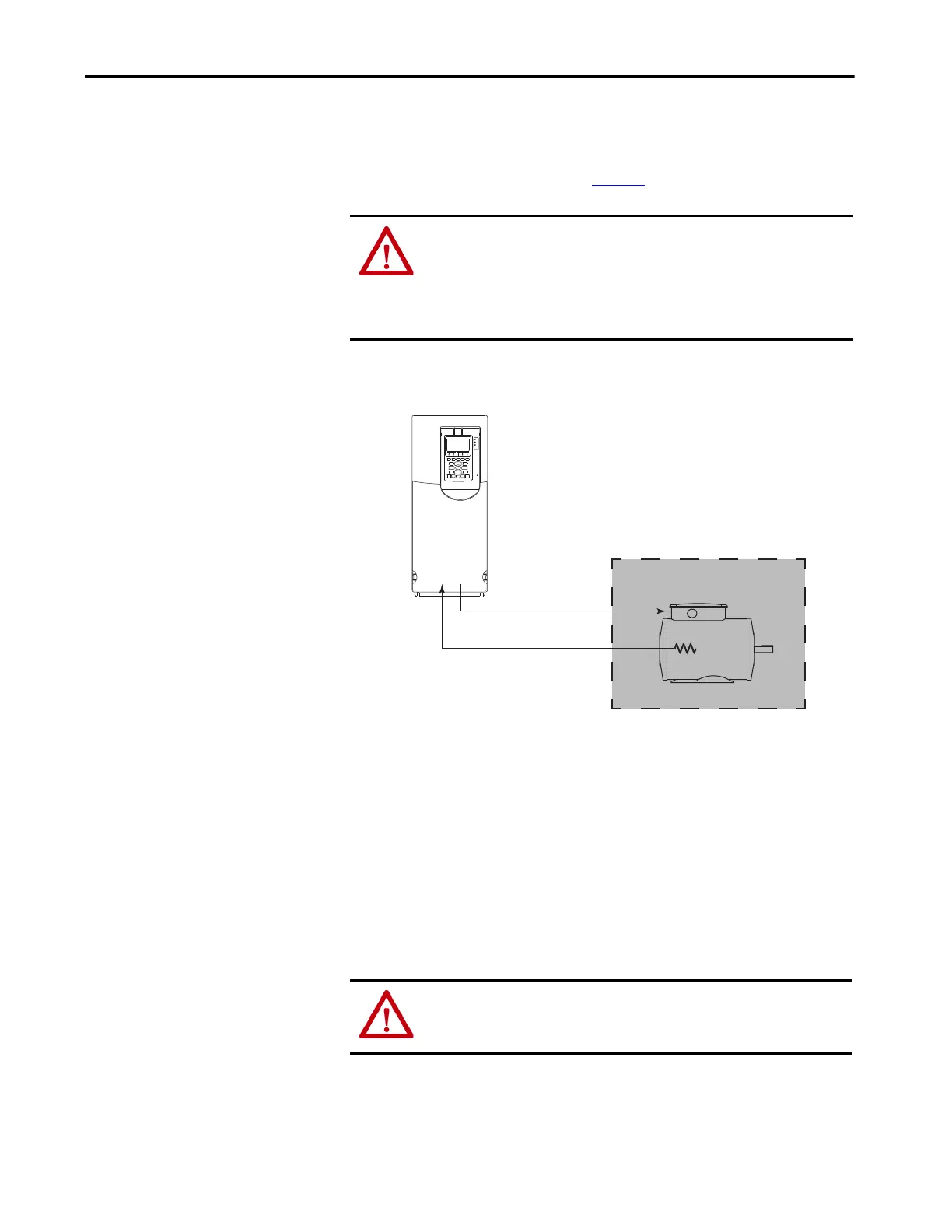
Describes the overall ATEX system architecture including motor and drive integration.

ATEX Function

Details the safety function of the ATEX option module for over-temperature protection.

Chapter 2 Installation and Wiring

Perform a Risk Assessment of the Operational Environment

Emphasizes conducting a risk assessment of the installation environment before setup.

Perform a Safety Analysis of the Motor

Highlights the importance of a safety analysis for the motor in ATEX applications.

Installation Requirements

General requirements for installing the ATEX option module assembly into the drive.

Install the ATEX Option Module Assembly

Detailed steps for installing the complete ATEX option module assembly into the drive.

Chapter 3 Verify Operation

Motors with Thermostatic Switches

Details ATEX motors with thermostatic switches and their functional testing.

Motors with Positive Temperature Coefficient (PTC) Devices

Details ATEX motors with PTC devices and their functional testing.

Functional Proof Testing without a Test Fixture

Method for performing functional testing of the ATEX safety function without a test fixture.

Chapter 4 ATEX Monitoring

Parameter 41 [ATEX Sts]

Details the functionality and bit meanings of the ATEX Status parameter (Parameter 41).

ATEX Fault Descriptions

Lists common ATEX-specific faults, their descriptions, and corrective actions.

ATEX Configuration Errors

Lists potential ATEX configuration conflicts and their resolutions.

Related product manuals