Rockwell Automation Publication 750-UM003D-EN-P - March 2017 21
Installation and Wiring Chapter 2
Configure the Hardware
The ATEX option module can be used in two different configurations:
• ATEX option module and 11-Series I/O option module that is used
without an additional safety option module. See page 23
.
• ATEX option module and 11-Series I/O option module that is used
with an additional safety option module, such as a Safe Torque Off
(catalog number 20-750-S) or Safe Speed Monitor (catalog number
20-750-S1) option module. See page 24
.
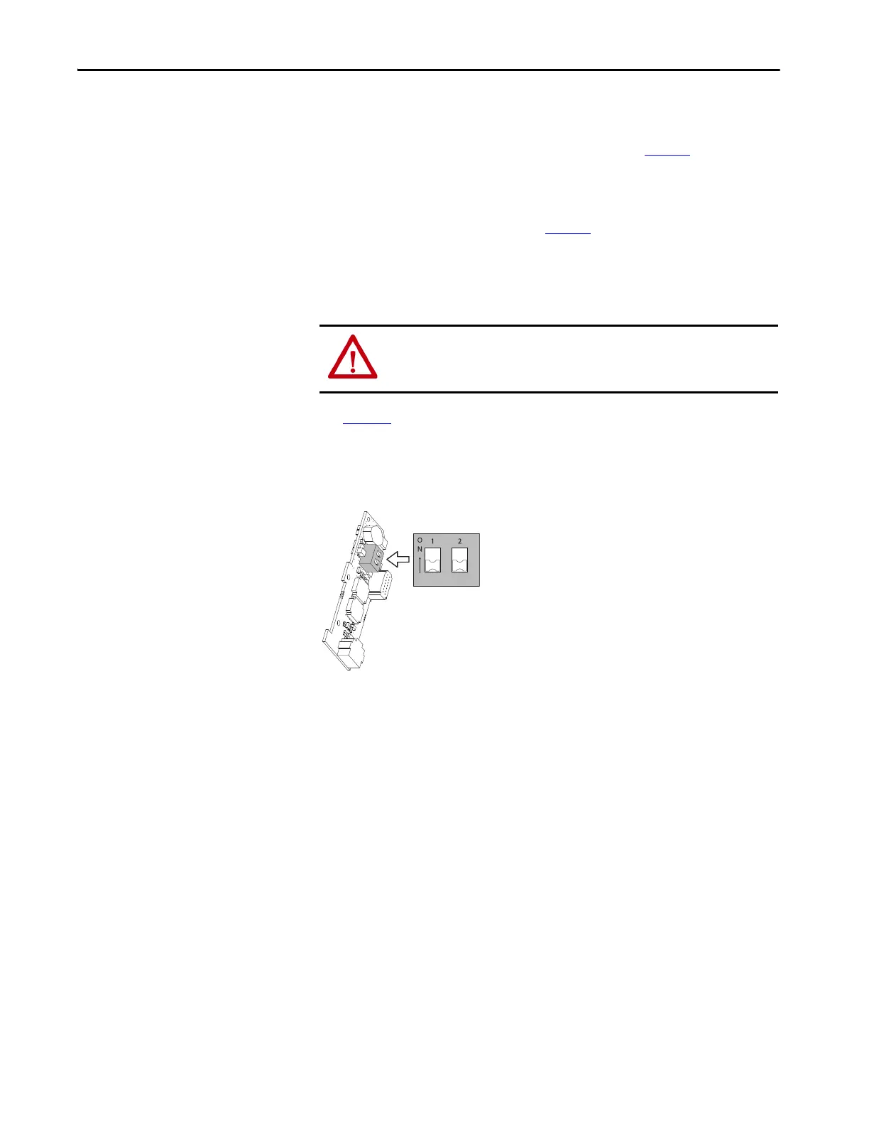
S1 Switch Location
See Figure 3 for the location of the S1switches on the ATEX option module:
• S1-1 is the safety configuration switch.
• S1-2 is the thermal sensor switch.
Figure 3 - ATEX Option Module S1 Switch Location
ATTENTION: Hazard of electric shock exists. Do not remove the insulation
wrapper from the ATEX option module. Removal of the insulation wrapper
can cause an electric shock hazard, and can cause damage to the drive.
S1-1
S1-2
In this diagram, the ATEX option module is
shown without the insulation wrapper.
Do not remove the insulation wrapper
from the ATEX option module.

 Loading...


