Rockwell Automation Publication 750-UM003D-EN-P - March 2017 27
Installation and Wiring Chapter 2
Installation Requirements
Installation must meet the radio frequency (RF) emission compliance and
installation requirements that are outlined in the installation instructions:
• PowerFlex 750-Series AC Drives Installation Instructions,
publication 750-IN001
.
• PowerFlex 750-Series Products with TotalFORCE Control Installation
Instructions, publication 750-IN100
.
• PowerFlex 755TM IP00 Open Type Kits Installation Instructions,
publication 750-IN101
.
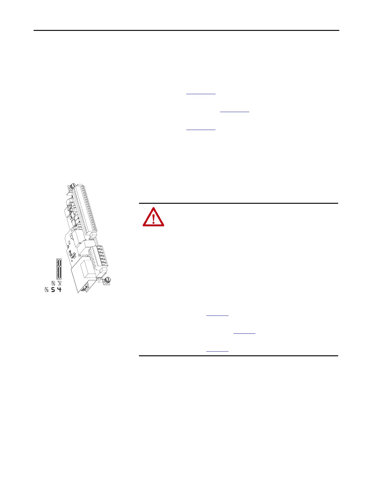
Install the ATEX Option
Module Assembly
To install the ATEX option module with 11-Series I/O option module
assembly in the drive, follow these steps.
1. Remove power from the drive and verify that the voltage on the bus
capacitors has discharged.
ATTENTION: To avoid an electric shock hazard, verify that the voltage on the
bus capacitors has discharged completely before performing any service.
Frames 1…7: Measure the DC bus voltage at the power terminal block by
measuring between the +DC and -DC terminals or between the +DC and -DC
test points if equipped. Also measure between the +DC terminal or test point
and the chassis and between the -DC terminal or test point and the chassis. The
voltage must be zero for all three measurements.
Frames 8…12: Measure the DC bus voltage at the DC+ and DC- test point
sockets on the front of the power module.
For the location of the terminal block and test point sockets, see the manual for
your drive:
• PowerFlex 750-Series AC Drives Installation Instructions,
publication 750-IN001
• PowerFlex 750-Series Products with TotalFORCE Control Installation
Instructions, publication 750-IN100
• PowerFlex 755TM IP00 Open Type Kits Installation Instructions,
publication 750-IN101

 Loading...


