9
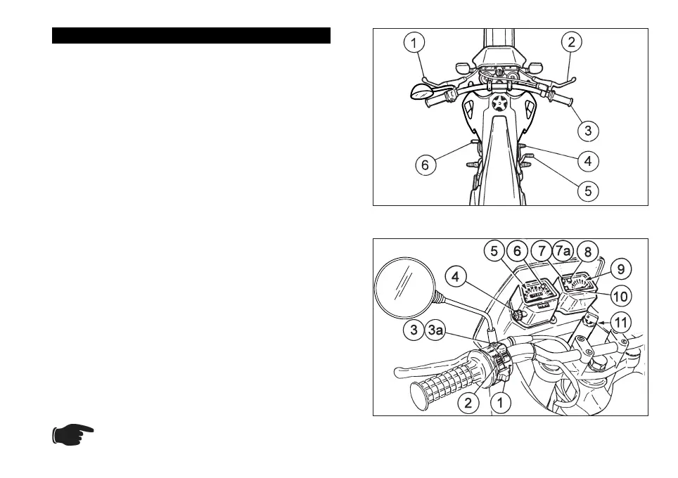
ARRANGEMENT OF THE CONTROLS
The control devices are positioned as indicated in fig-
ures 3 and 4, as follows:
Fig. 3
1) Clutch lever
2) Front brake lever
3) Twist grip
4) Rear brake pedal
5) Kick-starter
6) Gear pedal
Fig. 4
1) Turn indicator switch ()
2) Horn push button (
)
3) Dimmer light switch (
- ) and low beam si-
gnalling push button (
)
3a)
Dimmer light switch (
- ) and high
beam signalling push button (
)
4) Trip odometer control knob
5) Speedometer/odometer with trip counter
6) Mixer oil reserve warning light (
)
7) Low beam warning light (
)
7a) High beam warning light (
)
8) Neutral indicator warning light ()
9) Revolution counter (rpm)
10) Turn indicator warning light (
)
11) Ignition switch / steering lock / light switch
(
- - - )
Remember: 1 mile = 1.6 km
1 km = 0.625 miles
Fig. 3
Fig. 4
 Loading...