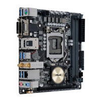
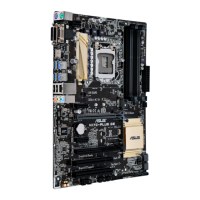
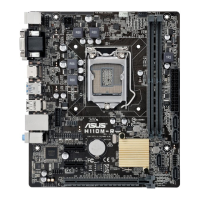
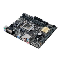
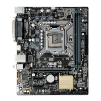
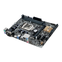
ASUS H170I-PRO
1-3
•
WerecommendthatyouuseanEATX12VSpecication
2.0-compliantpowersupplyunit(PSU)withaminimumof300W
powerrating.ThisPSUtypehas24-pinand8-pinpowerplugs.
•
DONOTforgettoconnectthe4-pinEATX+12Vpowerplug.
Otherwise,thesystemwillnotbootup.
• WerecommendthatyouuseaPSUwithhigherpoweroutput
whenconguringasystemwithmorepower-consumingdevices
orwhenyouintendtoinstalladditionaldevices.Thesystemmay
become unstable or may not boot up if the power is inadequate.
•
If you are uncertain about the minimum power supply
requirementforyoursystem,refertotheRecommended
PowerSupplyWattageCalculatorathttp://support.asus.com/
PowerSupplyCalculator/PSCalculator.aspx?SLanguage=en-us for
details.
EATXPWR
PIN 1
GND
+5 Volts
+5 Volts
+5 Volts
-5 Volts
GND
GND
GND
PSON#
GND
-12 Volts
+3 Volts
+3 Volts
+12 Volts
+12 Volts
+5V Standby
Power OK
GND
+5 Volts
GND
+5 Volts
GND
+3 Volts
+3 Volts
EATX12V
PIN 1
+12V DC
+12V DC
GND
GND
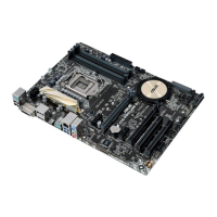
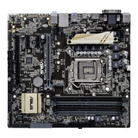
5. DDR4 DIMM slots
Install2GB,4GB,8GB,and16GBunbufferednon-ECCDDR4DIMMsintothese
DIMMsockets.
Formoredetails,refertoSystem memory.
3. Intel
®
LGA1151 CPU socket
ThismotherboardcomeswithasurfacemountLGA1151socketdesignedforthe
6thGenerationIntel(R)Core(TM)i7/Core(TM)i5/Core(TM)i3,Pentium(R)and
Celeron(R)processors.
Formoredetails,refertoCentral Processing Unit (CPU).
To erase the RTC RAM:
1. TurnOFFthecomputerandunplugthepowercord.
2. Useametalobjectsuchasascrewdrivertoshortthetwopins.
3. PlugthepowercordandturnONthecomputer.
4. Holddownthe<Del>keyduringthebootprocessandenterBIOS
setup to re-enter data.
Ifthestepsabovedonothelp,removetheonboardbatteryandshortthetwopinsagainto
cleartheCMOSRTCRAMdata.AfterclearingtheCMOS,reinstallthebattery.
CLRTC
+3V_BAT
GND
4. Clear RTC RAM (2-pin CLRTC)
ThisheaderallowsyoutocleartheRealTimeClock(RTC)RAMinCMOS.Youcan
cleartheCMOSmemoryofdate,andsystemsetupparametersbyerasingtheCMOS
RTCRAMdata.TheonboardbuttoncellbatterypowerstheRAMdatainCMOS,which
include system setup information such as system passwords.
 Loading...