Installation & Servicing instructions ATAG A-Series
20
The ue must be terminated in a place not likely to cause a nuisance.
For horizontal sections, the outlet system should always be tted on an incline (50 mm/m)
sloping down towards the appliance so that no condensation water is able to accumulate
in the outlet system. The chances of icicles forming on the roof outlet is minimised
by causing the condensation water to run back towards the appliance. In the case of
horizontal outlets the inlet system should be tted on an incline sloping down towards
the outside to prevent rainwater from coming in.
The appliance produces a white wisp of condensate (plumeing). This wisp of condensation
is harmless, but can be unattractive, particularly in the case of outlets in outside walls.
For wall terminals a plume management kit is available as an option.
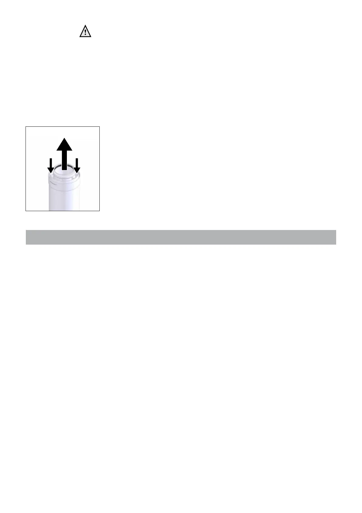
Cutting the pipe goes as follows:
- Cut just as much from the air intake part as from the ue gas part using a hand saw;
- Take off the burrs from the cutting edge to prevent cutting the seals;
When mounting the ue gas system, pay attention to the ow direction (See gue 6.8.e).
It is not permitted to mount a system upside down and will lead to complaints.
Use a soap solvent or special grease to simplify the tting.
6.8.1 Dimensioning of the ue gas and air intake duct
The ue diameter is determined by the total length of the run, including for the connection
pipe, elbows ttings and terminal covers etc and the type and number of boilers installed
into the system.
An undersized ue pipe can lead to disorders. Look at table 6.8.1.a for the choice of the
system and the correct diameter. The table below shows the maximum ue lengths with
the different boiler outputs. A longer ue gas length can be achieved by increasing the
diameter to ø 100mm.
Explanation table 6.8.1.a:
Two pipe ue gas system: maximum noted length = distance between boiler and
terminal A
Concentric ue gas system: maximum noted length = distance between boiler and
terminal B
When using bends the noted value behind every bend should be deducted from the
maximum straight length.
Flue
Air Air
Flow direction Figure 6.8.e
 Loading...