Installation & Servicing instructions ATAG A-Series
9
6 Connecting the boiler
The boiler has the following connection pipes;
- The central heating pipes.
These can be connected to the installation by means of compression ttings / adapter
ttings;
- The gas pipe.
It is provided with a female thread into which the tail piece of the gas valve can be
screwed;
- The condensation drain pipe.
It consists of a 22mm plastic pipe. The drain pipe can be connected to this by means
of an open connection. If the open connection is tted in a different location, then the
pipe can be lengthened by means of a 32 mm PVC sleeve;
- The ue gas exhaust system and air supply system.
It consists of a concentric connection 60/100 mm.
- Cold and hot water pipes.
Only Combi boilers: These consist of 15 mm copper pipe and can be connected to
the installation by means of compression ttings / adapter ttings.
It is recommended that isolation valves are tted to all heating and hot water
connections to facilitate ease of future maintenance.
It is advisable to spray-clean all of the boiler’s connecting pipes and/or to spray-
clean/blow-clean the installation before connecting it to the boiler.
6.1 Central heating system
Connect the central heating system according to the current regulations.
The boiler pipes can be connected to the installation by means of compression ttings.
For connecting to thick-walled pipe (welded or tted), adapters should be used.
When removing the plastic sealing caps from the pipes, contaminated testing
water may be released.
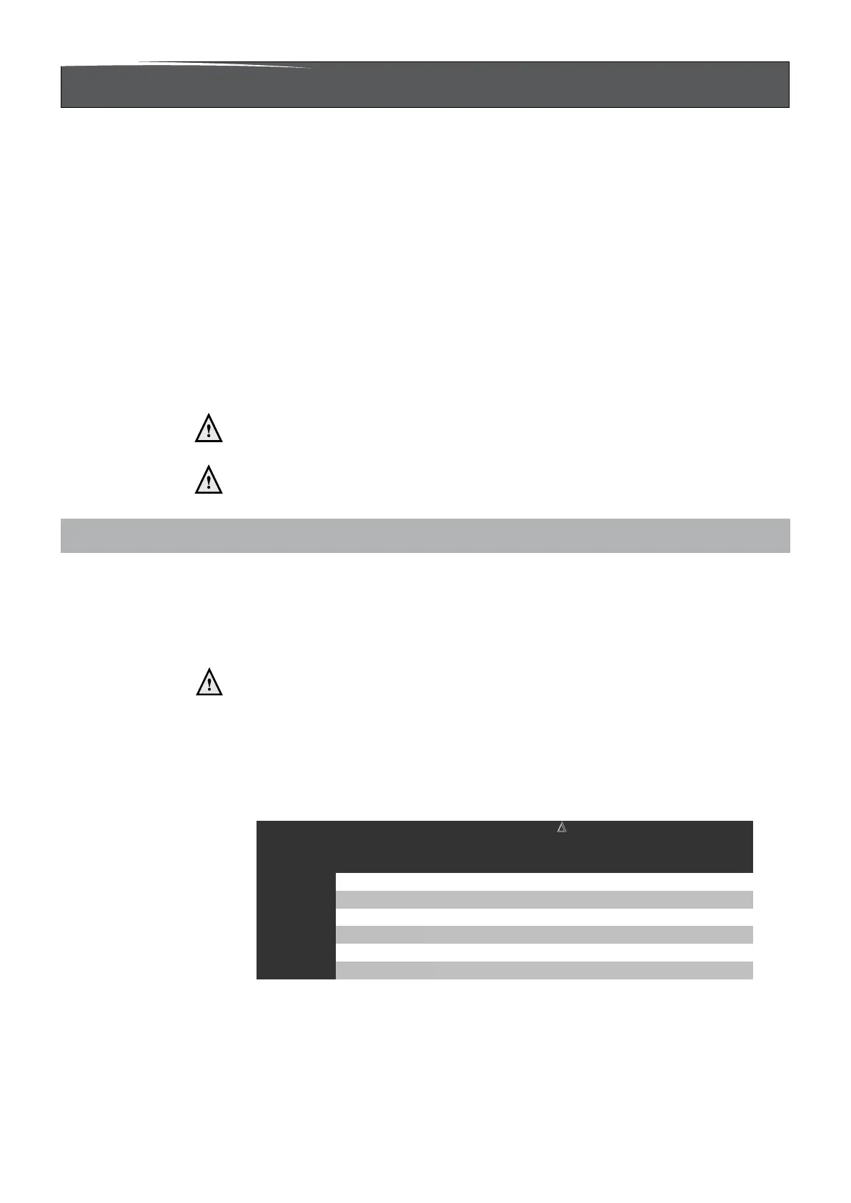
The boiler has a self-adjusting and self-protecting control system for the load. This
involves checking the temperature difference between the supply and return water. Table
6.1.a shows the water displacement of the circulation pump can deliver for a particular
installation resistance.
Boile
type l/min l/h kPa mba
A203C UPM2 15-70 12,7 760 25 250
A325C UPM2 15-70
20,3 1220 25 250
A325EC
UPM2 15-70
20,3 1220 25 250
A200S UPM2 15-70 12,7 760 25 250
A320S UPM2 15-70
20,3 1220 25 250
Water flow rate at
T
20°C
Permissible installation
resistancePump type
Installation resistance table 6.1.a
 Loading...