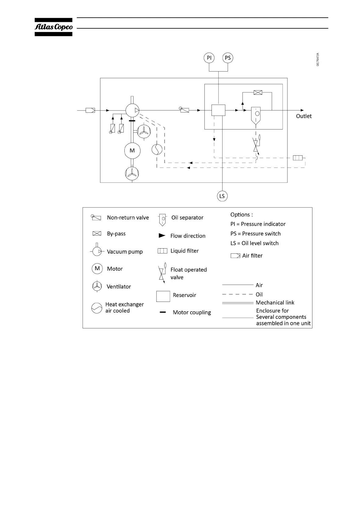
Figure 9 Flow diagram - GVS 470A and GVS 630A
3.4. Oil flow
Oil injected into the pump chamber serves to seal, lubricate and cool the pump.
The oil entrained with the compressed gas is coarsely trapped in the bottom part
of the oil casing. Oil is finely filtered in the integrated exhaust filter elements. The
proportion of oil in the exhaust gas is reduced below the visibility threshold (over
99 % entrapment rate). The oil trapped in the exhaust filters is returned to the
generator via an oil return line. To prevent the entry of gas, flowing at
atmospheric pressure from the oil reservoir, into the intake port the oil return line
is controlled by a float valve. The oil cycle is maintained by the pressure
difference between the oil casing (pressure above atmospheric pressure) and the
intake port (pressure below atmospheric pressure).
12/2021 - ©Atlas CopcoPage 236996022430_C
Description
 Loading...