- 28 -
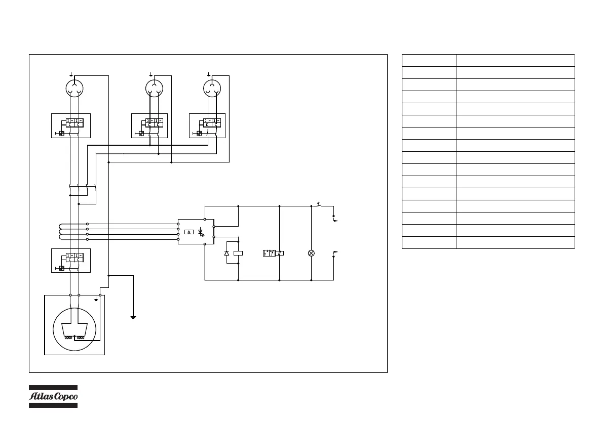
GENERATOR 110V WITHOUT AUTOMATIC CONTROL SYSTEM
Circuit diagram (9822 1055 27) (Not on HardHat)
X3
3L1
3L2
L2L1
16A
e54
c0c0
X2
L2L1
16A
H3
A1
A2
K5
52
51
S7
P
B
R
Y2
K5
1
2
3
4
V
W
V1
W1
1L1
1L2
2L1
2L2
50A
Q1
b3
G
G3
VW
14
12
3
13
b6 b6
12
b6
b3
b6
b3
13
12
12
b3
13
35
34
e54
c0c0
e54
e0e0
f0f0
f0f0
e0e0
e0e0
e0e0
e54
5
6
7
8
X1
L2L1
32A
32A
Q2
16A
Q3
16A
Q4
13
b3
L1
L2
b6
12
b3
I n
30mA
40msec
4
5
6
7
10
11
1
3
N13
D1
e0
e0
1
2
3
4
T13
EARTHING PIN
To Circuit diagram
9822 0991 34
Reference Name
D1 Diode
G3 Generator
H3 Lamp (Power ON)
K5 Contactor
N13 Earth faultcurrent relay
Q1 Main circuit breaker 2-pole
Q2 Circuit breaker 2-pole
Q3 Circuit breaker 2-pole
Q4 Circuit breaker 2-pole
S7 Switch (Generator-compressor)
T13 Current transformer for N13
X1 Socket outlet
X2 Socket outlet
X3 Socket outlet
Y2 Solenoid valve (Generator action)
The compressor is equipped with a negative earthed
system.
For location of relais K1, K2, K3, K4, see paragraph
Electric system.
 Loading...