- 38 -
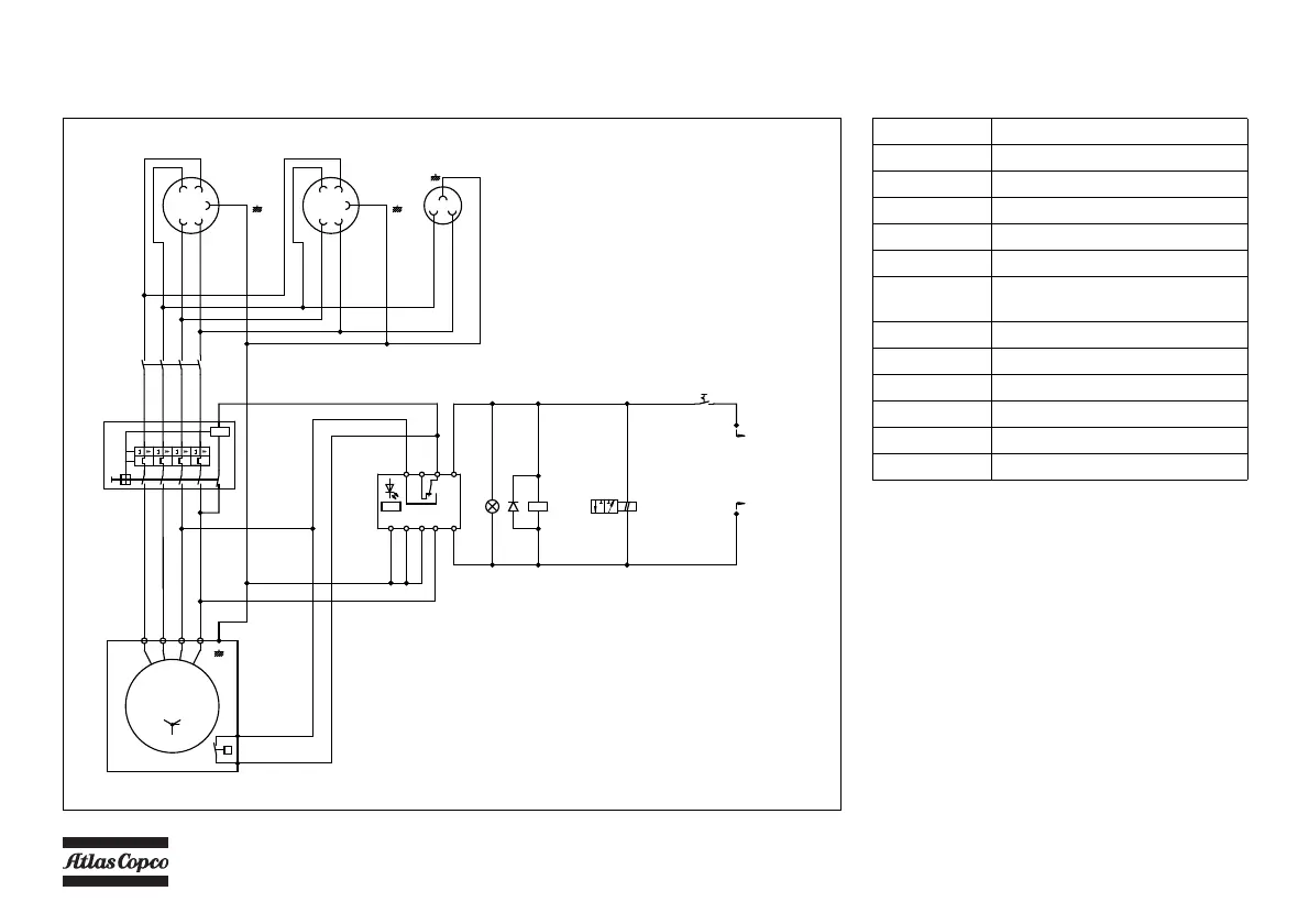
GENERATOR 230/400V, 12 kVA WITHOUT AUTOMATIC CONTROL SYSTEM
Circuit diagram (9822 1055 28) (Not on HardHat)
X1.2
L1
L2
L3
N
NL3
L2 L1
16A
c54c6c0c0c0
X1.3
L2
N
NL3
16A
c54
c6c0
X1.1
L1
L2
L3
N
N
L3
L2
L1
16A
G
NW1V1U1
G3
c54c6c0c0c0
C6
C6
C0
C0
C0
C0
C0
C0
EA
K5
1
2
3
4
5
6
7
8
U
V
W
V1
U1
W1
N
N
16A
Q1
16A 16A 16A
N
b0
b0
W1
b54
b0
b54
b54
16
b0
N
b6
16
W1
b0
b0
16
b6
W1
H3
S6
u
A1
A2
K5
35
52
51
S7
P
B
R
Y2
13
13
12
3
13
b6 b6
12
b6
b3
34
12
b6
12
b3
b3 b3
13
b6
12
b3
L A2
A1
PE
TR
14
12
11
R<
K6
D1
To Circuit diagram
9822 0991 34
Reference Name
D1 Diode
G3 Generator
H3 Lamp (Power Control)
K5 Contactor/4-pole
K6 Insulation monitoring relay
Q1 Main circuit breaker 4-pole +
shunt tripcoil
S6 Thermalcontact
S7 Switch (Generator-compressor)
X1.1 Socket outlet
X1.2 Socket outlet
X1.3 Socket outlet
Y2 Solenoid valve (Generator action)
The compressor is equipped with a negative earthed
system.
For location of relais K1, K2, K3, K4, see paragraph
Electric system.
 Loading...