- 42 -
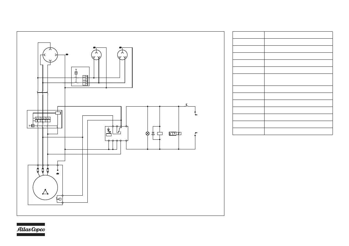
GENERATOR 230V, 12 kVA
Circuit diagram (9822 1055 29) (Not on HardHat)
To Circuit diagram
9822 0991 34
H3
S6
u
EA
A1
A2
K5
52
51
S7
P
B
R
Y2
K5
1
2
3
4
5
6
X1.3
1L1
1L2
L2L1
16A
c54
c0c0
U1
V1
W1
1V1
1U1
1W1
W1
X1.1
X1.2
L1
L2
L3
1L1
1L2
L3
L2
L1
32A
L2L1
16A
32A
Q1
32A 32A
b3
G
G3
U2 V2W2
U1 V1 W1
c54
c0c0
e54
e0e0e0
e0e0e0
e0e0e0
b0
13
13
W1
V1
16
12
3
13
b6 b6
12
b6
b3
b0
b6
b6
b3
V1
13
12
12
b3
16
b0
16
b0
V1
35
34
c0
c0
b54
b0
b6
12
b54
b54
b3b0b0
L
A2
A1
PE
TR
14
12
11
R<
K6
16A
16A
Q2
L1
L2
D1
Reference Name
D1 Diode
G3 Generator
H3 Lamp (Power Control)
K5 Contactor/4-pole
K6 Insulation monitoring relay
Q1 Main circuit breaker 3-pole +
shunt tripcoil
Q2 Circuit breaker 2-pole
S6 Thermalcontact
S7 Switch (Generator-compressor)
X1.1 Socket outlet
X1.2 Socket outlet
X1.3 Socket outlet
Y2 Solenoid valve (Generator action)
The compressor is equipped with a negative earthed
system.
For location of relais K1, K2, K3, K4, see paragraph
Electric system.
 Loading...