CHAPTER6 Hardware Maintenance
Mediant 1000 Gateway & E-SBC | Hardware Installation Manual
b. Loosen the two screws using your fingers or a flat-head screwdriver.
c. Grip and pull the two screws of the Fan Tray module to gently slide the module out of
the chassis slot.
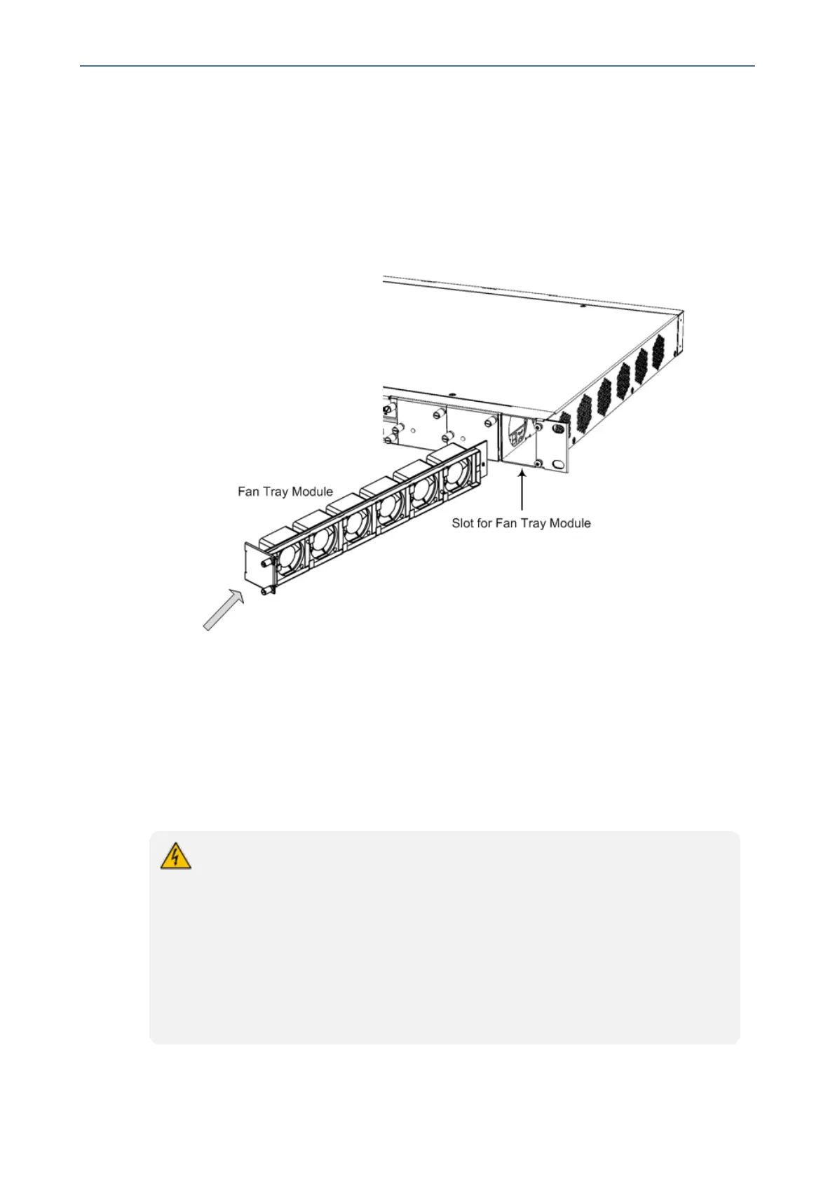
2. Install the new Fan Tray module:
a. Align the module with the guiding rails located in the chassis slot.
Figure 6-18: Installing Fan Try Module
b. Gently push the module into the slot until it is engaged with the chassis backplane and
the module's front panel is flush with the chassis front panel plate.
c. Using your fingers or a flat-head screwdriver, tighten the two captive screws on the
front panel of the Fan Tray module to secure the module to the chassis.
Power Supply Module
This section describes how to install and replace the Power Supply modules.
● When using only one Power Supply module, the second AC power socket on the
rear panel is covered by a plastic sticker. Please do not remove the sticker and
connect anything to this power socket. Remove the sticker only when two Power
Supply modules are used.
● Correct insertion of the Power Supply module into the chassis slot is crucial in
preventing irreversible hardware damage to the module (and more specifically, to
the capacitor) and resulting in the inability to operate and power the chassis. To
avoid damaging the module, when inserting or removing the Power Supply
module from the chassis slot, ensure that you adhere to the following
precautions:
- 69 -

 Loading...


