CHAPTER6 Hardware Maintenance
Mediant 1000 Gateway & E-SBC | Hardware Installation Manual
✔ Keep the module aligned with the slot's guiding rail.
✔ Keep the module lifted up towards the roof of the slot so that the base of the
module does not touch the floor of the slot (and damage the electrical
components located on the underside of the module). Below shows incorrect
insertion where the underside components collide with the chassis:
Installing an Optional, Secondary Power Supply Module
The procedure below describes how to install the optional, secondary (spare) Power Supply
module.
➢ To install the spare Power Supply module:
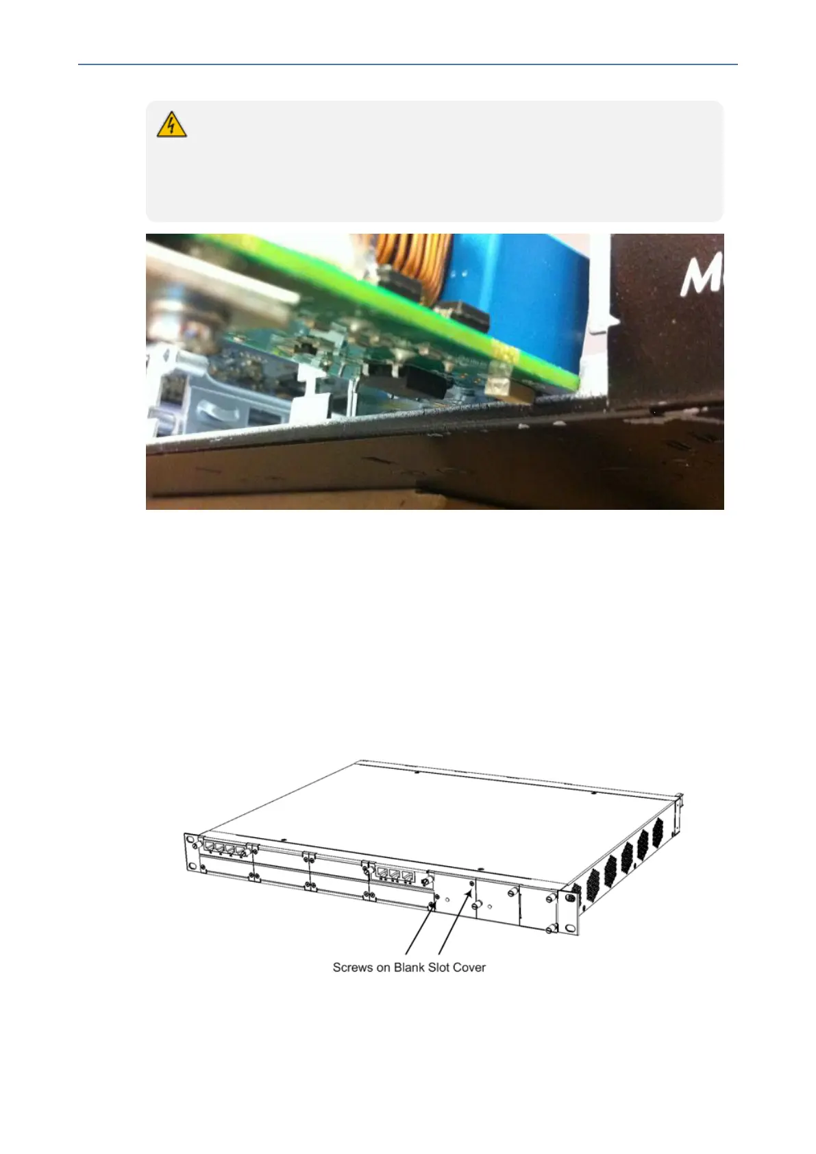
1. On the front panel, remove the blank panel covering the slot intended for housing the
second Power Supply module, as shown in the following figure. To do this, use a Philips
screwdriver to remove the two screws securing the blank panel to the chassis.
Figure 6-19: Screws on Blank Panel Cover
2. Hold the Power Supply module in the orientation as shown in the following figure, and then
gently and carefully insert the module into the slot, by sliding the module along the slot's
- 70 -

 Loading...


