J-17
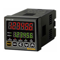
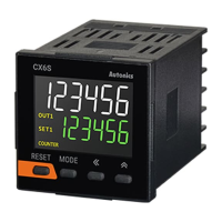
LCD Display Counter/Timer
(A)
Photoelectric
Sensors
(B)
Fiber
Optic
Sensors
(C)
Door/Area
Sensors
(D)
Proximity
Sensors
(E)
Pressure
Sensors
(F)
Rotary
Encoders
(G)
Connectors/
Connector Cables/
Sensor Distribution
Boxes/Sockets
(H)
Temperature
Controllers
(I)
SSRs / Power
Controllers
(J)
Counters
(K)
Timers
(L)
Panel
Meters
(M)
Tacho /
Speed / Pulse
Meters
(N)
Display
Units
(O)
Sensor
Controllers
(P)
Switching
Mode Power
Supplies
(Q)
Stepper Motors
& Drivers
& Controllers
(R)
Graphic/
Logic
Panels
(S)
Field
Network
Devices
(T)
Software
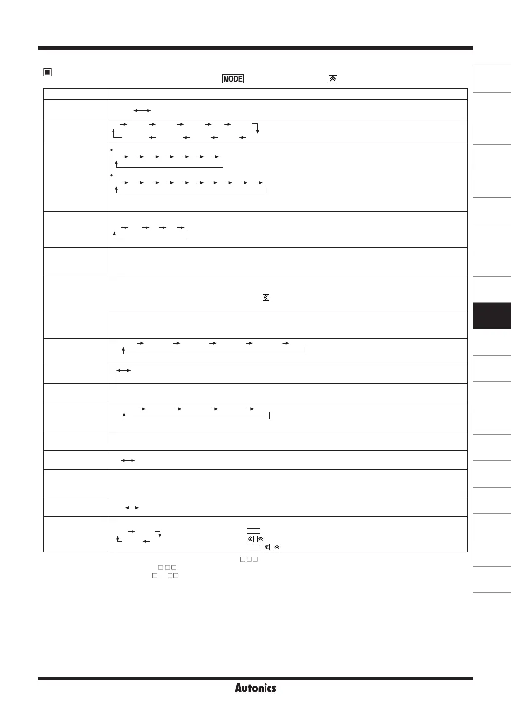
Parameter Setting (Counter)
(
key: moves parameters,
key: changes parameter setting value)
※
1: For voltage input (PNP), no-voltage input (NPN) model (CX6 - ).
※
2: For free voltage input model(CX6
-
F), these parameters do not appear due to fixed setting.
※
3: For 1-stage setting model (CX6 -1P
)
,
OUT1
does not appear.
The
OUT2
output time is displayed as
OUtT
.
※
4: Decimal point and prescale decimal point
-Decimal point: Set the decimal point for display value regardless of prescale value.
-Prescale decimal point: Set the decimal point for prescale value of counting value regardless of display value.
Parameter Parameter setting value
Counter/Timer
[
C-T
]
COUNT
TIME
※
COUNT
: Counter
TIME
: Timer
Input mode
[
I
nM
]
UP
UD-C
※
1
UD-B
※
1
UD-A DN-3 DN-2
DN-1DNUP-1 UP-3UP-2
Output mode
[
OUt
M
]
Input mode is
UP
,
UP-1
,
UP-2
,
UP-3
or
DN
,
DN-1
,
DN-2
,
DN-3
,
F PKN R[ Q A
Input mode is
UD-A
,
UD-B
※
1
,
UD-C
※
1
F PKN R[
Q A S T D
※
If max. counting speed is 5kcps, and output mode is
D
, max. counting speed is automatically changed as 30cps,
factory default.
Max. counting
speed
※
2
[
CPS
]
30 1300 5K1K
※
Max. counting speed is when duty ratio of INA or INB input signal is 1:1.
It is applied for INA, or INB input as same.
※
When output mode is
D
, set max. counting speed one among 1cps, 30cps, 300cps, or
1kcps.
OUT 2
output time
※
3
[
OUT2
]
※
Set one-shot output time of OUT 2.
※
Setting range: 00.01 to 99.99 sec
※
When output mode is
F
,
N
,
S
,
T
,
D
, this parameter does not appear. (xed as HOLD)
OUT 1
output time
※
3
[
OUT1
]
※
Set one-shot output time of OUT 1.
※
Setting range: 00.01 to 99.99 sec, Hold
※
When number of tens digit is ashing, press the key once and
HOLD
appears.
※
When output mode is
S
,
T
,
D
, this parameter does not appear. (xed as HOLD)
OUT
output time
※
3
[
OUtT
]
※
Setting range: 00.01 to 99.99 sec
※
When output mode is
F
,
N
,
S
,
T
,
D
, this parameter does not appear. (xed as HOLD)
Decimal point
※
4
[
DP
]
------ --.---- -.----------.- ---.-------.--
※
Decimal point is applied to PV and SV.
Min. reset time
※
2
[
R
ESET
]
1 20
, unit: ms
※
Set min. width of external reset signal input.
Input logic
※
2
[
SIG
]
NPN
: No-voltage input,
PNP
: Voltage input
Prescale
decimal point
※
4
[
S
ClDP
]
-.----- --.---------.- ---.-------.--
※
Decimal point of prescale should not set smaller than decimal point [
DP
].
Prescale value
[
SCL
]
※
Setting range: 0.00001 to 99999.9
※
Setting range of prescale is linked with prescale decimal point [
SClDP
] setting.
TOTAL counter
※
1
[
T
OTAL
]
ㅐㅐON OFF
Start point value
[
S
TART
]
※
Setting range of start point value is linked with decimal point [
DP
] setting. (0.00000 to 999999)
※Wheninputmodeis
DN
,
DN-1
,
DN-2
, this parameter
doesnotappear.
※WhentotalcountfunctionisON,thisp
arameter does not appear.
※
1
Memory protection
[
DATA
]
CLR REC
※
CLR
: Resets the counting value when power OFF.
REC
: Maintains the counting value when power OFF. (memory protection)
Key lock
[
LOCK
]
lOFF LOc1
LOc3 LOc2
※
lOFF
: Unlock keys, key lock indicator turns OFF
LOc1
: Locks
RESET
key, key lock indicator turns ON
LOc2
: Locks , keys, key lock indicator turns ON
LOc3
: Locks
RESET
, , keys, key lock indicator turns ON
 Loading...