70 • Reference Section
MultiClamp 700A Theory and Operation, Copyright 2000, 2001 Axon Instruments, Inc.
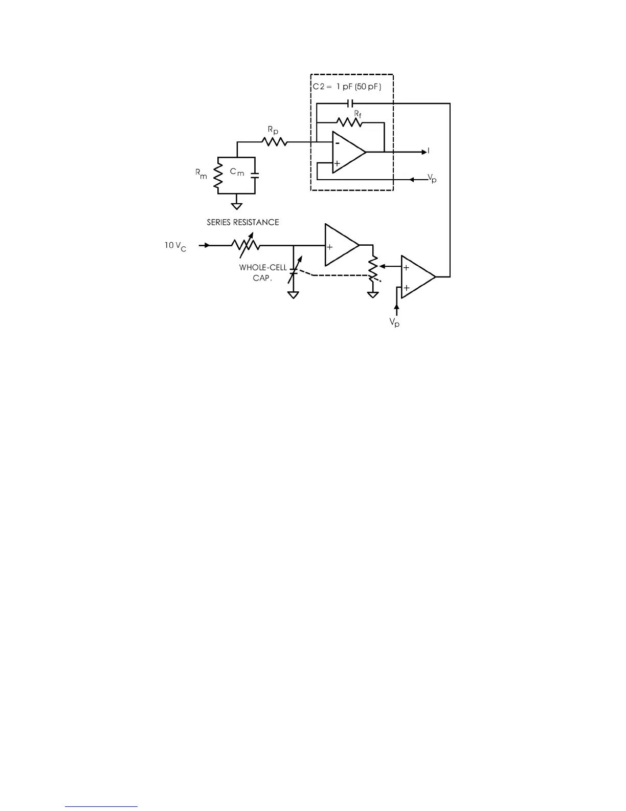
Figure 4.7. Whole-cell capacitance compensation circuit.
Assume that the fast and slow electrode compensation controls have already been set to
compensate for C
p
. By appropriately adjusting the SERIES RESISTANCE and
WHOLE CELL CAP values in this circuit, the current injected through C2 will supply
the transient membrane current (I). These adjustments do not alter the time constant
for charging the membrane. Their function is to offload the burden of this task from
the feedback resistor, R
f
. In many cells, even a small command voltage (V
c
) of a few
tens of millivolts can require such a large current to charge the membrane that it cannot
be supplied by R
f
. The headstage output saturates for a few hundred microseconds or a
few milliseconds, thus extending the total time necessary to charge the membrane.
This saturation problem is eliminated by appropriate adjustment of whole-cell
capacitance compensation. This adjustment is particularly important during series
resistance correction since it increases the current-passing demands on R
f
. By moving
the pathway for charging the membrane capacitance from R
f
to C2, the series
resistance compensation circuitry can operate without causing the headstage input to
saturate. (See also Chapter 5,
SERIES RESISTANCE COMPENSATION.)
 Loading...