Reference Section • 71
Chapter 5
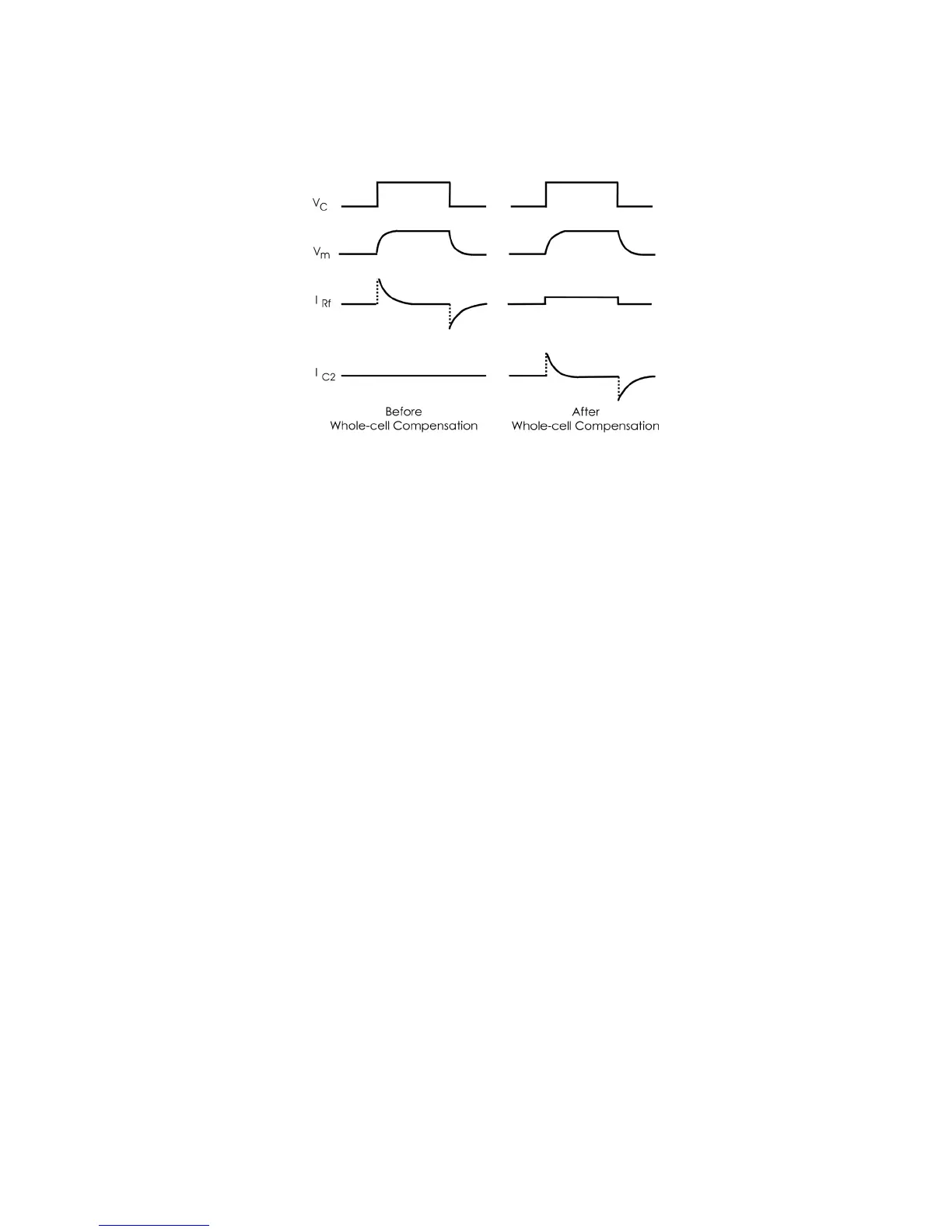
The effect of transferring the current-passing burden from R
f
to C2 is illustrated in
Figure 4.8.
After perfect whole-cell compensation is applied, the current to charge the membrane
capacitor is removed from the I
Rf
trace and only the steady state current remains. All
of the transient current appears in the I
C2
trace. (The I
C2
trace in the figure was
recorded using an oscilloscope probe connected to the internal circuitry). The
Membrane Current and Command Potential outputs on the MultiClamp 700A would
look like the I
Rf
and V
c
traces, respectively (Figure 4.8). It is easy to mistakenly think
that the time course for charging the membrane is very fast but this is clearly not the
case. Use of an independent electrode in the cell would show that the cell charging
rate is not affected by these adjustments.
The pF and M values found by the MultiClamp Commander for optimal whole cell
compensation provide estimates of the cell capacitance and the series resistance,
respectively. However, these estimates are accurate only if the cell input resistance is
significantly greater than R
s
.
Figure 4.8. Using the injection capacitor to charge the membrane capacitance.
 Loading...