Actuator Azbil Corporation
3-2 Model VFR - FloWing Eccentric Rotary type Control Valves
3-2 : Adjusting the actuator
The actuator requires to be adjusted if its action starts to shift or after it has been
overhauled. Before adjusting the actuator, turn the manual handwheel to the fully
clockwise position as viewed from the direction indicator plate. (See Figure 3-14)
(1) Connect the air piping to the actuator through a pressure regulator.
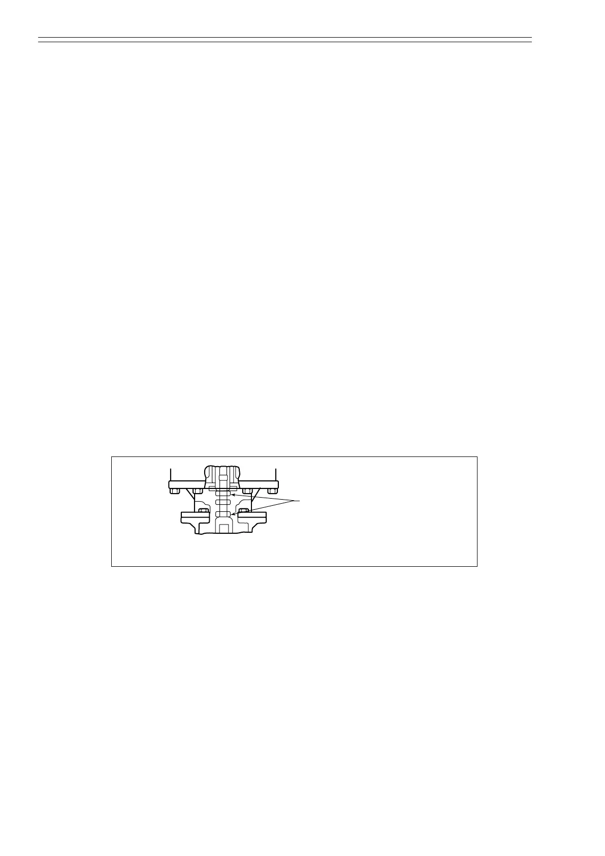
(2) Loosen the lock nuts on the turnbuckle and then loosen* the turnbuckle.
~Note
*: Of the turnbuckle, the fork side is with a right-handed thread and the
actuator side is with a left-handed thread. (See Figure 3-2 and Figure
3-4)
(3) By adjusting the pressure regulator, apply to the actuator a pressure corresponding
to the upper limit of the spring range if the valve is in direct-action mode or a
pressure corresponding to the lower limit of the spring range if the valve is in
reverse-action mode.
(4) Use a wrench to rotate the hex section of the turnbuckle until rotation becomes
heavy and the parts on the clamp shaft do not turn any further. The turning
directions are as follows:
• For a direct-action valve, turn the spring compression nut clockwise*.
• For a reverse-action valve, turn the lock nut counterclockwise*
(*: As viewed from the position shown in Figure 3-2.)
(5) As is align the pointer with the S index of the scale.
(6) Securely tighten the lock nuts of the turnbuckle.
(7) For the adjustment of the positioner, see “Chapter 4 : Valve Positioner”.
Lock nuts
(Top: left-hand thread;
bottom: right-hand thread)
Figure 3-2

 Loading...

