Installation Azbil Corporation
1-2 Model VFR - FloWing Eccentric Rotary type Control Valves
1-2 : Installation on piping
(1) Before installing the valve, remove scale, welding chips and other foreign
material from both the upstream and downstream sides of the piping.
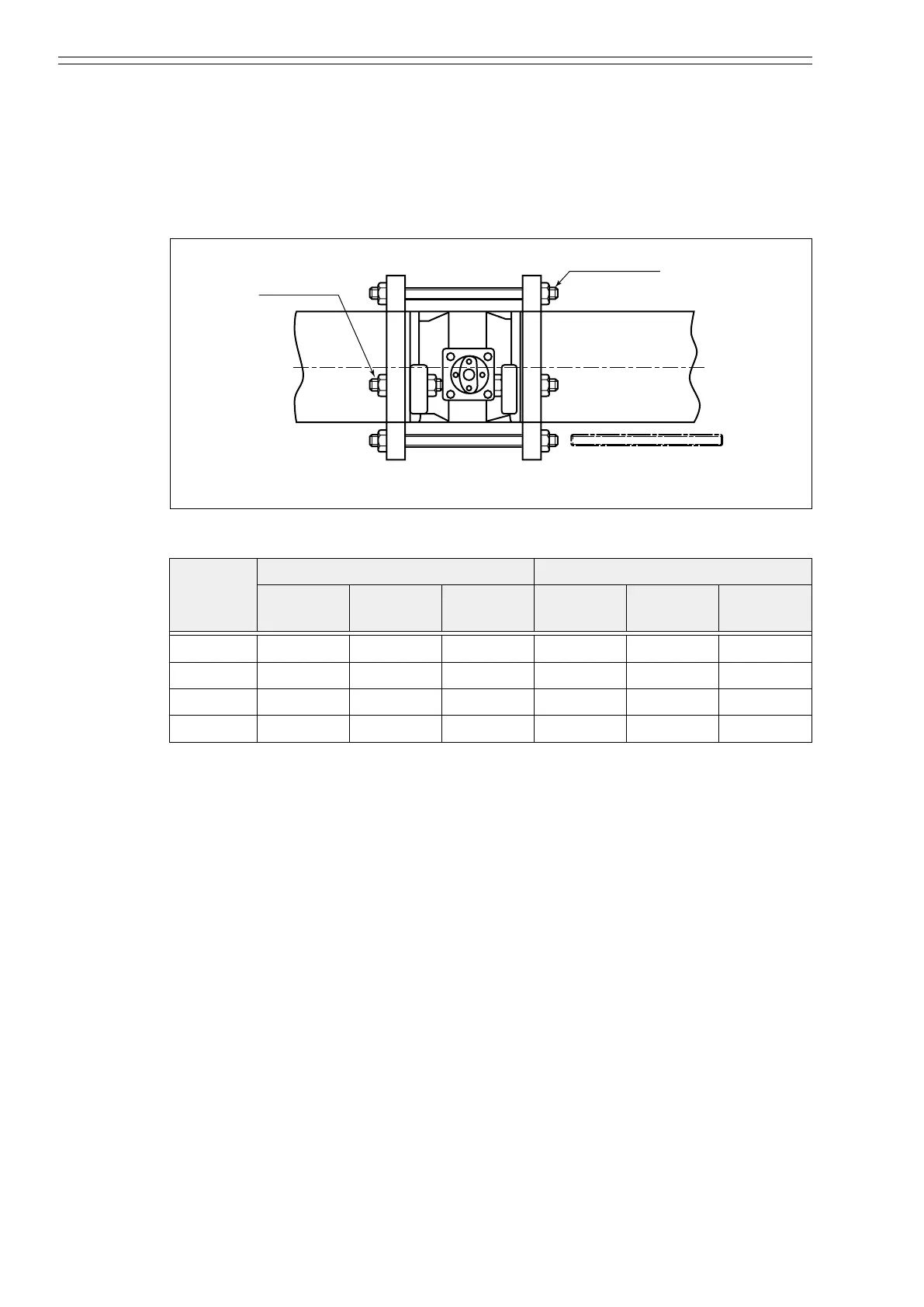
(2) Pass the longer bolts through the lower half of the anges to make up a cradle for
the valve and place the valve on the cradle.
Short bolt
Figure 1-2 Valve installation in piping
Table 1-1 Valve installation in piping
Valve size
(inches)
Longer bolts Shorter bolts
JIS 10K
ANSI 150
JIS 20K ANSI 300
JIS 10K
ANSI 150
JIS 20K ANSI 300
6 M20 × 350 M22 × 370 M20 × 380 M20 × 130 M22 × 140 M20 × 150
8 M20 × 380 M22 × 380 M22 × 410 M20 × 130 M22 × 130 M22 × 160
10 M22 × 440 M24 × 450 M27 × 490 M22 ×140 M24 × 160 M27 × 190
12 M22 × 480 M24 × 500 M30 × 540 M22 × 140 M24 × 160 M30 × 200
(3) Place the gasket for piping and pass the longer bolts through the upper half of the
anges. For the mounting bolts, see Figure 1-2, and Table 1-1.
~Note
Use the shorter bolts in such places where the longer bolts will interfere
with the packing box.
(4) Align the center of the valve with that of the piping and tighten the bolts evenly.
(5) Make sure that the direction of the arrow mark stamped on the valve body
conforms with the direction of the process uid ow in the piping.
(6) Pay attention so that the piping connection gaskets do not protrude into the
inside of the piping. Be sure to use gaskets of materials suitable to the type and
temperature of the uid to be controlled.
(7) After installing the valve and connecting the air piping, blow the air piping clean
to remove any dust and foreign material from inside the air piping.
(8) Do not install any heating or cooling provisions for the bonnet section.
~Note
The mounting attitude of the valve can be changed by altering the mounting
position of the actuator. See “Chapter 5 : Changing the mounting attitude of
actuator and type of valve action” for procedures.

 Loading...

