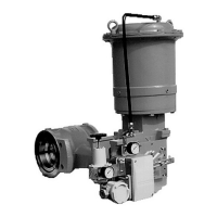
Azbil Corporation Changing the mounting attitude of actuator and type of valve action
Model VFR - FloWing Eccentric Rotary type Control Valves 5-1
Chapter 5 : Changing the mounting
attitude of actuator and
type of valve action
The mounting attitude of the model VFR valves actuator can be changed and the type
of its action can be modied without requiring any additional parts.
5-1 : Changing the mounting attitude of actuator
The actuator can be installed in any one of the four attitudes shown in Figure 5-1. The
standard mounting attitudes are positions 1 and 5 shown in Figure 5-1. If the actuator
is to be installed in an attitude other than the standard attitudes, take precautions not
to let water get into and entrapped inside the actuator.
(1) Remove the actuator from the valve body by following the steps described in
“Chapter 3 : Actuator”.
(2) While securely holding the actuator, remove the mounting-bolts of the yoke and
bracket. (See Figure 3-1.) Set the actuator to the desired attitude and x the yoke
and bracket with the mounting-bolts.
(3) Fix the actuator to the valve body by following, in the reverse order, the
procedures in Step (1) above. Make certain that the roller of the clamp is correctly
set on the hand-wheel shaft.
(4) Adjust the actuator by referring to subsection “3-2 : Adjusting the actuator”. For
the positioner, refer to subsection “4-2-6 : Adjusting the positioner”.
5-2 : Changing the valve action
(1) Flatten the anti-rotation tting of the lock nut of the fork. (See Figure 3-4.)
(2) Remove the bolts (hex-hole head) from the clamp and remove the clamp from the
valve stem. (See Figure 3-4.)
(3) Change the poisoning of the clamp and fork by referring to Figure 3-9.
(4) Remove the connecting-bolts from the intermediate bracket and main bracket, and
change their positioning as shown in Figure 5-3.
(5) Flip over the direction indicator plate of the handwheel. Make certain that the
plate indicates the correct directions for the direct action or the reverse action.
(See Figure 5-4.)
(6) For assembly, follow the above disassembly procedure in the reverse order.
When valve actions are changed between direct action and reverse action, the position
of the air piping connection port also is changed. Remove the diaphragm case (top)
once and change their position as required.

 Loading...