Azbil Corporation Valve Positioner
Model VFR - FloWing Eccentric Rotary type Control Valves 4-7
4-2-5 : Removing and installing the positioner
Removal
(1) Disconnect the air piping from the positioner.
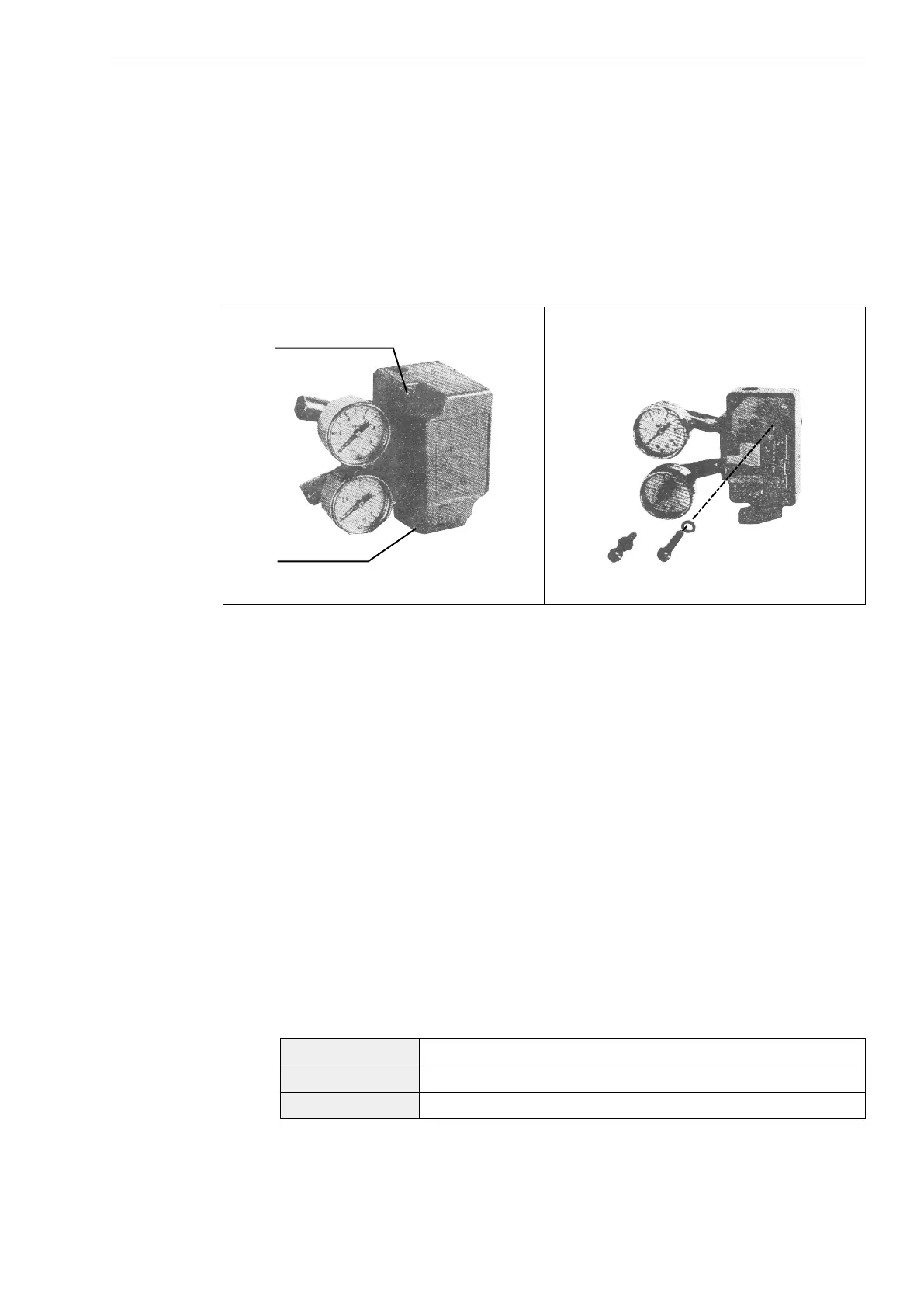
(2) Loosen the two clamping-bolts (M5, hex-hole head) with a hex wrench (4 mm)
and remove the positioner cover. (See Figure 4-13.)
(3) Loosen the two inner clamping-bolts (M6. hex-hole head) with a hex wrench (5
mm). The positioner is now ready for removal. (See Figure 4-14.)
Bolt M5
Hexagonal head bolt
Positioner cover
Figure 4-13 Figure 4-14
Installation
For the adjustment of a positioner after its installation has been completed, see
subsection “4-2-6 : Adjusting the positioner”.
(1) Conrming the actuator specications and cam characteristics
By referring to the nameplate, conrm the following three items:
(a) Direct action (air-to-close) or reverse action (air-to-open)
(b) Spring range of the actuator
(c) Cam characteristics
(2) Installing the indicator and cam
(a) Connect the air piping to the actuator and apply an air pressure referring
to the table shown below. When this is done, the valve will be fully closed
irrespective of the type of actuator action (direct action or reverse action).
(Example: If the actuator is of the reverse action type and the spring range is
98 to 200 kPa {1 to 2 kg/cm²}, apply an air pressure of 98 kPa {1 kg/cm²} to
the actuator.)
Valve action Air pressure applied to actuator
Direct action A pressure corresponding to upper limit of actuator spring
Reverse action A pressure corresponding to lower limit of actuator spring

 Loading...

