Installation
40 Mono Power Unit BUM 62 T
5.99009.03 Baumüller Nürnberg GmbH
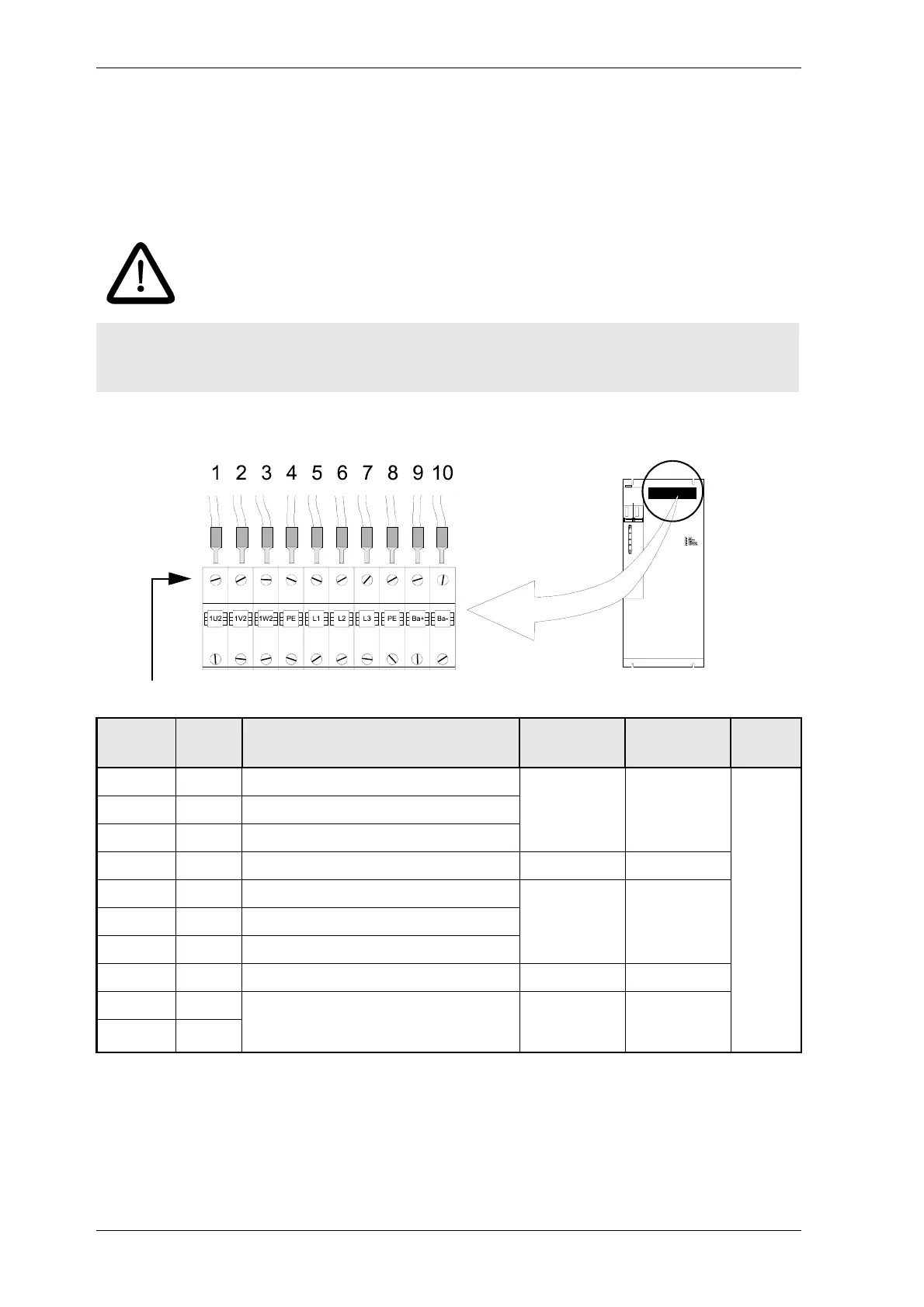
6.6 Terminal strips and plug-in terminals
6.6.1 Power connections
Terminal strip X1
Screw connections for cable with wire crimp
1. Position
2. Voltage range (r.m.s. value)
3. Current range (r.m.s. value)
4. select the connection cross-section according to the applicable standards depending on the
application. The specified values indicate which flexible conductors are safely connected.
DANGER
Danger to life!
The permissible connection value (see ”Technical data”) must never be exceeded.
Termina
l
Pos.
1)
Description
U
range
2)
I
range
3)
A
4)
1U2 1 Motor connection phase U max. 570 V max. 130 A 10 - 25
mm
2
8 - 4
AWG
1V2 2 Motor connection phase V
1W2 3 Motor connection phase W
PE 4 Earth connection
L1 5 Mains connection phase L1 400 V -15 %
up to
460V +10%
max. 105A
L2 6 Mains connection phase L2
L3 7 Mains connection phase L3
PE 8 Earth connection
Ba+ 9 Connection regenerative resistor
Ba+ is internally connected to ZK+, Ba- is
connected to the collector of the brake switch.
between
Ba+ and Ba-
max. 800 V
DC
max. 73 A
Ba- 10
 Loading...