5.0 Installation
30
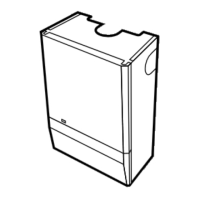
5.19 Water Connections
1. The boiler has two side water connections, the
top connection being FLOW and the bottom
connection being RETURN (Fig. 75).
2. It is essential that FLOW and RETURN pipes
are connected to the correct fittings.
3. The top flow connection incorporates the boiler
thermostat, overheat thermostat and a venting
point (Fig. 76).
4. A copper elbow, compression nut and olive are
provided in the kit for the return connection.
NOTE: Drain cocks should be fitted to all the
system's low points.
5. Connect the two electrical tags of the thermostat
lead to the connections on the thermostat - either
wire can be connected onto either connection -
there is no polarity (Fig. 76).
6. Remove the overheat thermostat and clip from
the plastic kit bag. Engage the thermostat in the
clip as shown (Fig 76). Prise the clip over the flow
pipe as near to the vent as possible (Fig. 76 & 77).
7. Connect the two electrical tags from the wiring
harness to the terminals on the overheat
thermostat (Fig.77) - either wire can be connected
onto either terminal - there is no polarity.
5.20 Pipe Routes
1. Ensure that any pipework is routed so as to
leave the boiler via the spaces at the rear of the
outer case, either at the top or at the bottom.
2. Pipes may be dropped down within the outer
case in the spaces between the back plate and the
combustion box.
NOTE: It is important that the pipework does
not interfere with the correct fitting of the outer
case and a space of 14mm clearance must be
left between any vertical pipes and the outer
edge of the back plate.
5.21 Gas Connection
1. Connection to the gas supply is RC
1
/
2
(
1
/
2
in
BSPT internal) located at the rear of the gas cock
(Fig. 78).
2. When connecting the gas feed pipe, the control
box may be pulled forward to give greater access.
Fig. 75
Fig. 78
Venting Point
Plastic
Shroud
in place
Fig. 76
Boiler Thermostat
Overheat
Thermostat
Thermostat Clip
Flow Pipe
Orange Leads
Fig. 77
 Loading...