List of illustrations
BK3xx0 89Version: 4.3.0
List of illustrations
Fig. 1 BK3120 and LC3100 - Bus Couplers for PROFIBUS DP ............................................................ 9
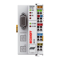
Fig. 2 BK3150 - Bus Coupler for PROFIBUS DP ................................................................................. 11
Fig. 3 BK3500 and BK3520 - Bus Couplers with optical fiber connection for PROFIBUS DP............... 13
Fig. 4 Spring contacts of the Beckhoff I/O components......................................................................... 18
Fig. 5 Dimensions, using BK3120 and LC3100 as examples................................................................ 19
Fig. 6 Release the locking mechanism by pulling the orange tab.......................................................... 20
Fig. 7 Groove and tongue of the housings............................................................................................. 20
Fig. 8 Standard wiring............................................................................................................................ 21
Fig. 9 Pluggable wiring .......................................................................................................................... 21
Fig. 10 High Density Terminals................................................................................................................ 22
Fig. 11 Connecting a cable on a terminal point ....................................................................................... 23
Fig. 12 Potential groups of a Bus Terminal block .................................................................................... 24
Fig. 13 Power contact on the left ............................................................................................................. 25
Fig. 14 Power supply connections for BKxx00, BKxx10, BKxx20 and LCxxxx........................................ 26
Fig. 15 Power supply connections for BKxx50 and BKxx51 .................................................................... 27
Fig. 16 UL identification ........................................................................................................................... 27
Fig. 17 Potential connection diagram of an EKxxxx ................................................................................ 28
Fig. 18 Pin assignment M12 socket (-B310)............................................................................................ 29
Fig. 19 Pin assignment M12 socket/plug connector (-B318) ................................................................... 29
Fig. 20 Pin assignment of the PROFIBUS D-sub socket......................................................................... 29
Fig. 21 Pin assignment socket/plug connector Fieldbus Box modules.................................................... 30
Fig. 22 PROFIBUS cable assignment ..................................................................................................... 31
Fig. 23 Start-up behaviour of the Bus Coupler ........................................................................................ 35
Fig. 24 KS2000 configuration software.................................................................................................... 42
Fig. 25 TwinCAT System Manager.......................................................................................................... 44
Fig. 26 Configuration of the PROFIBUS DP I/O modules - selection of the PROFIBUS DP master PC
card.............................................................................................................................................. 45
Fig. 27 Configuration of the PROFIBUS DP I/O modules - inserting the bus nodes ............................... 45
Fig. 28 Configuration of the PROFIBUS DP I/O modules - appending the Bus Terminals...................... 46
Fig. 29 Busklemn.bmp ............................................................................................................................. 46
Fig. 30 Busklems.bmp ............................................................................................................................. 46
Fig. 31 Parameter data for the BK3120 ................................................................................................... 47
Fig. 32 Example for entering individual bytes. ......................................................................................... 48
Fig. 33 Example for entering associated bytes........................................................................................ 49
Fig. 34 Example for compact representation of the Bus Terminal KL3312 ............................................. 50
Fig. 35 Example for compact representation of the Bus Terminal KL3312 ............................................. 50
Fig. 36 Output data in the Bus Coupler ................................................................................................... 52
Fig. 37 Input data in the Bus Coupler ..................................................................................................... 52
Fig. 38 Configuration of the K-bus cycle for the DP couplers .................................................................. 53
Fig. 39 K-bus - Slow FreeRun mode (default setting).............................................................................. 53
Fig. 40 K-bus mode fast FreeRun............................................................................................................ 54
Fig. 41 K-bus - standard synchronous mode........................................................................................... 54
Fig. 42 K-bus - synchronous mode with optimized input update (one cycle)........................................... 55
Fig. 43 K-bus - synchronous mode with optimized input update (two cycles) ......................................... 55
 Loading...