Operation
EL2911 and EL2911-220036 Version: 2.0.0
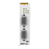
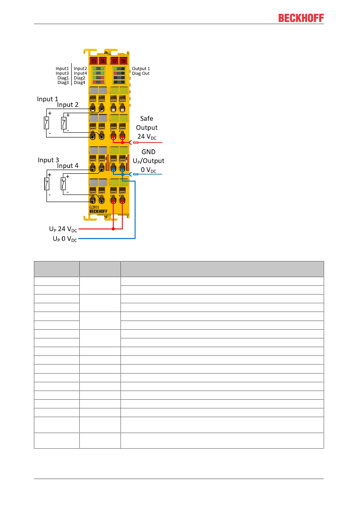
5.2.4.4 Connection
Fig.17: EL2911 - pin assignment
Terminal point Input / Out-
put
Signal
1 In1 Input 1+ (clock output)
2 Input 1- (safe input)
3 In3 Input 3+ (clock output)
4 Input 3- (safe input)
5 In2 Input 2+ (clock output)
6 Input 2- (safe input)
7 In4 Input 4+ (clock output)
8 Input 4- (safe input)
1‘ - not used
2‘ Out1 Safe output 1
3‘ - GND U
P
(0V
DC
for power supply and safe output)
4‘ - 24 V
DC
power supply U
P
5‘ - not used
6‘ Out1 Safe output 1
7‘ - GND U
P
(0V
DC
for power supply and safe output)
8‘ - 24 V
DC
power supply U
P
Power contact
(top)
Out1 Safe output 1
Power contact
(low)
- GND U
P
(0V
DC
for power supply and safe output)
 Loading...