Operation
EL2911 and EL2911-220046 Version: 2.0.0
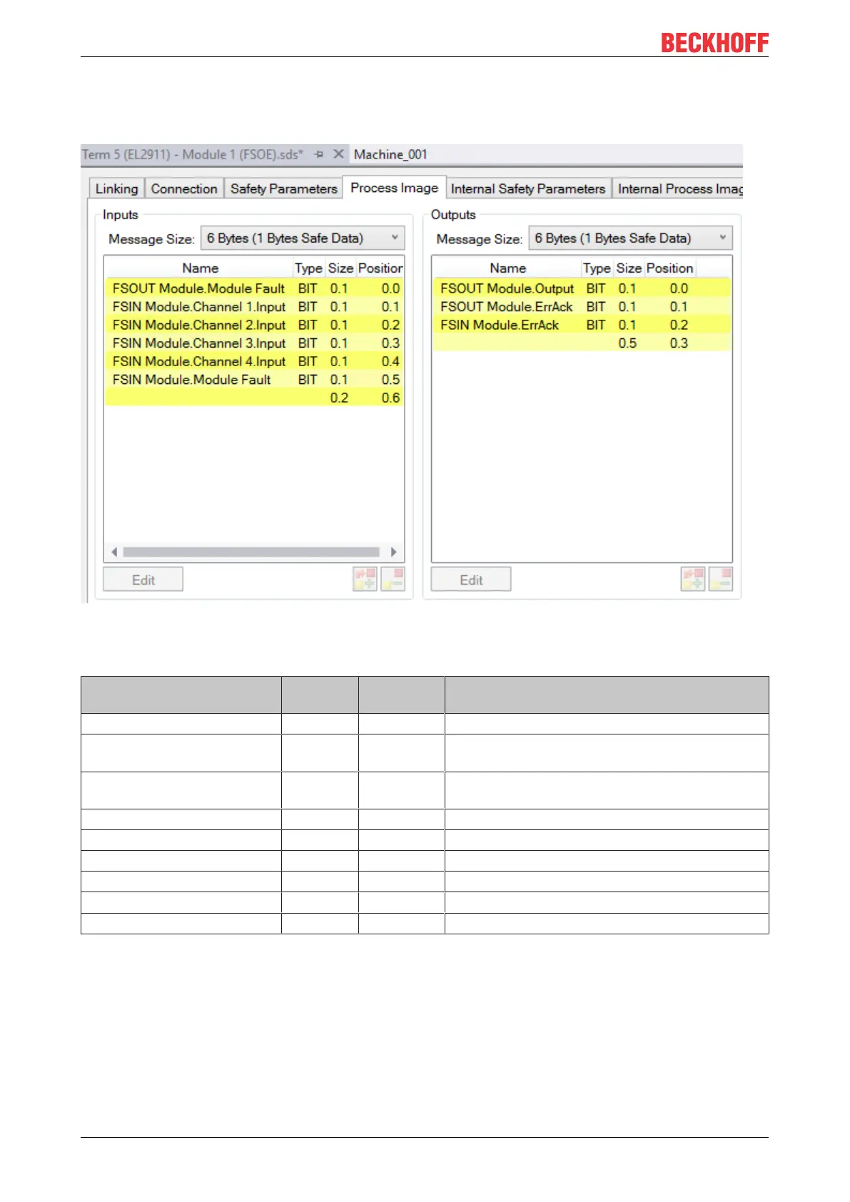
5.3.8 EL2911 process image
The process image of the EL2911 consists 6 bytes of process data in the input and the output.
Fig.28: EL2911 process image
The assignment of the individual signals in the safe data is listed in the following table.
Name Process
image
Bit position Description
FSOUT Module.Module Fault IN 0.0 Module error information for safe output
FSIN
Channel1.Channel1.Input
IN 0.1 Safe input channel 1
FSIN
Channel2.Channel1.Input
IN 0.2 Safe input channel 2
FSIN Module.Channel3.Input IN 0.3 Safe input channel 3
FSIN Module.Channel4.Input IN 0.4 Safe input channel 4
FSIN Module.Module Fault IN 0.5 Module error information for safe input module
FSOUT Module Output OUT 0.0 Safe output to power contact
FSOUT Module.ErrAck OUT 0.1 Error acknowledge for safe output module
FSIN Module.ErrAck OUT 0.2 Error acknowledge for safe input module
 Loading...