Mounting and wiring
EL6731 25Version: 2.8
Pin assignment M12 socket (-B310)
Fig.17: Pin assignment M12 socket (-B310)
Pin assignment M12 socket/plug connector (-B318)
Fig.18: Pin assignment M12 socket/plug connector (-B318)
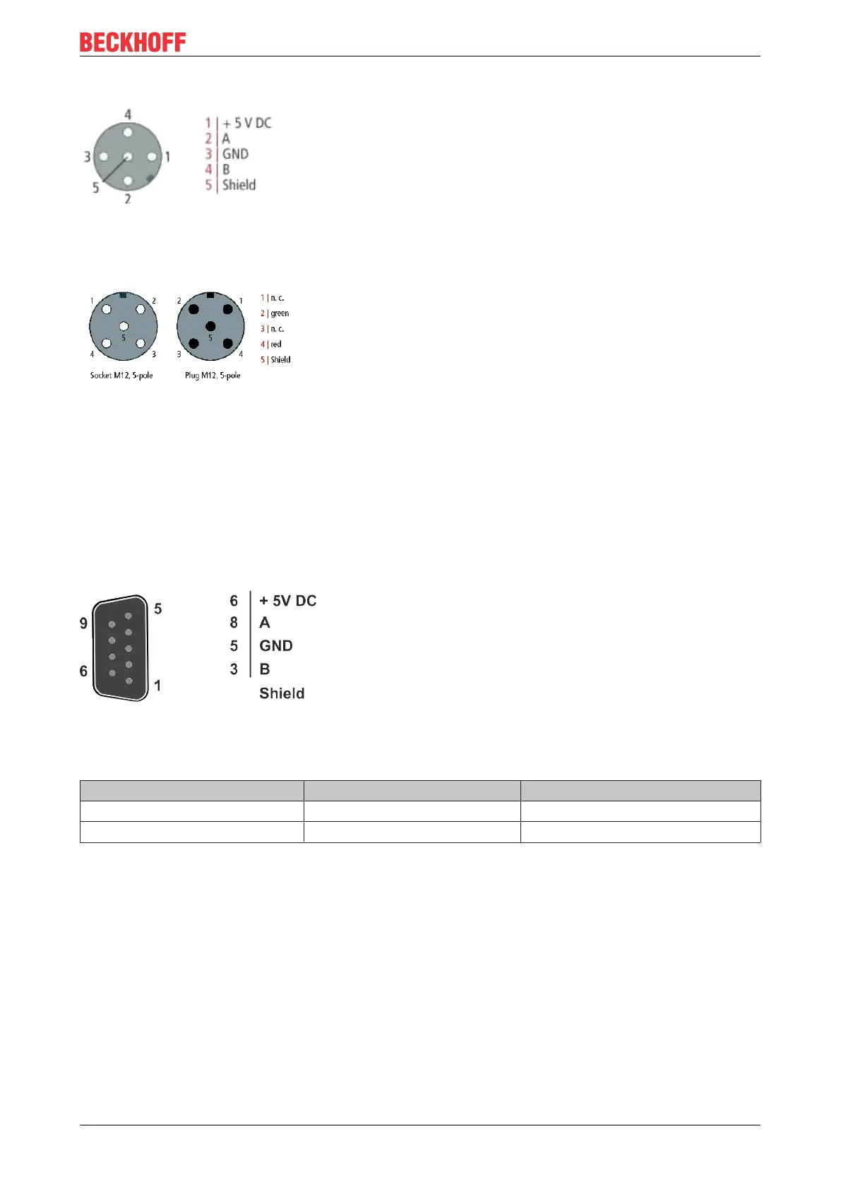
Nine-pin D-Sub
Pin 6 transfers 5V
DC,
pin 5 transfers GND for the active termination resistor. These must never be misused
for other functions, as this can lead to destruction of the device.
Pins 3 and 8 transfer the PROFIBUS signals. These must never be swapped over, as this will prevent
communication.
Pin assignment of the PROFIBUS D-sub socket
Fig.19: Pin assignment of the PROFIBUS D-sub socket
PROFIBUS wire colors
PROFIBUS line M12 D-Sub
B red Pin 4 Pin 3
A green Pin 2 Pin 8
Connection of the FieldbusBoxmodules
The FieldbusBoxmodules are connected either directly or via a T-piece (or Y-piece).
The B318 series features a socket and a plug connector, i.e. this is where the PROFIBUS is routed in the
module. The supply voltage (+5V
DC
) for the termination resistor is only present at the socket. The termination
resistor ZS1000-1610 is only available as a plug connector.
The incoming PROFIBUS line should always end with a socket.

 Loading...


