Product overview
EL9xxx 51Version: 3.9
Terminal point Description
Indication No.
+24 V* / 230 V AC** 1 Supply input + 24 V [EL9200, EL9210]
Supply input 230 V AC [EL9290: variable voltage, up to 230 V AC]
connected internally with terminal 4 and positive [EL9200, EL9210]
resp. 230 V AC [EL9290] power contact)
0 V* / N** 2 0 V for supply input [EL9200, EL9210]
N for supply input [EL9290]
connected internally with terminal 5 and negative [EL9200, EL9210]
resp. neutral [EL9290] power contact)
PE 3 PE (connected internally with terminal 6 and PE power contact)
+24 V* / 230 V AC** 4 Supply input + 24 V [EL9200, EL9210]
Supply input 230 V AC [EL9290: variable voltage, up to 230 V AC]
connected internally with terminal 1 and positive [EL9200, EL9210]
resp. 230 V AC [EL9290] power contact)
0 V* / N** 5 0 V for supply input [EL9200, EL9210]
N for supply input [EL9290]
connected internally with terminal 2 and negative [EL9200, EL9210]
resp. neutral [EL9290] power contact)
PE 6 PE (connected internally with terminal 3 and PE power contact)
* only EL9200, EL9210
** only EL9290
LEDs
LED Color Meaning
Power LED** green off No input voltage at supply input
on 24 V
DC
at supply input
Error LED** red off Fuse OK
on Fuse error
** only EL9200, EL9210
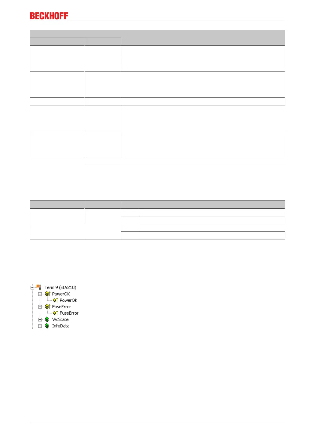
Process data (only EL9210)
The EL 9210 has a bit width of 2 bits (diagnosis bit for the power contacts voltage, "PowerOK" and diagnosis
bit for fuse error, "FuseError") and is displayed in the TwinCAT tree as follows:
Fig.37: EL9210 in the TwinCAT tree
If there is no voltage impressed on the power contacts, the corresponding diagnosis bit 'PowerOK' has
FALSE (0) status.
If there is a fuse error, the corresponding diagnosis bit 'FuseError' has TRUE (1) status.

 Loading...


