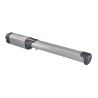
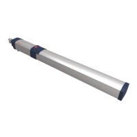
Turn the power off.•
Place batteries • (a) on the battery support base as shown
in Fig. 12. Cut a hole in the black rubber cap (b) to allow
wires in.
Run battery wire (++ red and -- black) into the provided •
black sheath. Disconnect wire on terminal 4 on the Dei-
mos BT control board and run it through the hole. Run
through the hole provided wires (marked 55, 33, ++ and
--).
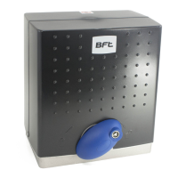
Keep SBS charger • (c) loose to facilitate wiring operation. Connect wire labeled ++ to #1 on the SBS charger,
wire labeled -- to #2 on the SBS charger, wire labeled 33 to #3 on the SBS charger and to #3 on the Deimos
BT board (this wire sill share #3 on the DEIMOS BT board with transformer wire, to facilitate wiring use
provided ferrule), connect wire originally connected to #4 on the Deimos BT board to #4 on the SBS charger,
wire labeled 55 on #5 on the SBS charger and on #4 on the Deimos BT board.
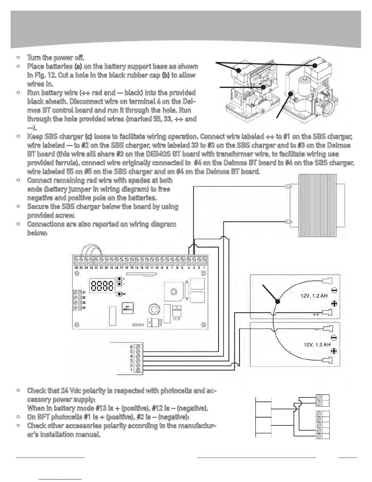
Connect remaining red wire with spades at both •
ends (battery jumper in wiring diagram) to free
negative and positive pole on the batteries.
Secure the SBS charger below the board by using •
provided screw.
Connections are also reported on wiring diagram •
below:
Check that 24 Vdc polarity is respected with photocells and ac-•
cessory power supply:
When in battery mode #13 is + (positive), #12 is – (negative).
On BFT photocells #1 is + (positive), #2 is – (negative):•
Check other accessories polarity according to the manufactur-•
er’s installation manual.
BATTERY BACKUP INSTALLATION
Technical Support: 1-877-995-8155
11
55
33
55
33
_ _
++
SBS
Battery jumper
2
1
5
4
3
2
1
13
12
(-)
(-)
(-)
(+)
(+)
(+)
(a)
(b)
(c)
FIG. 12
 Loading...