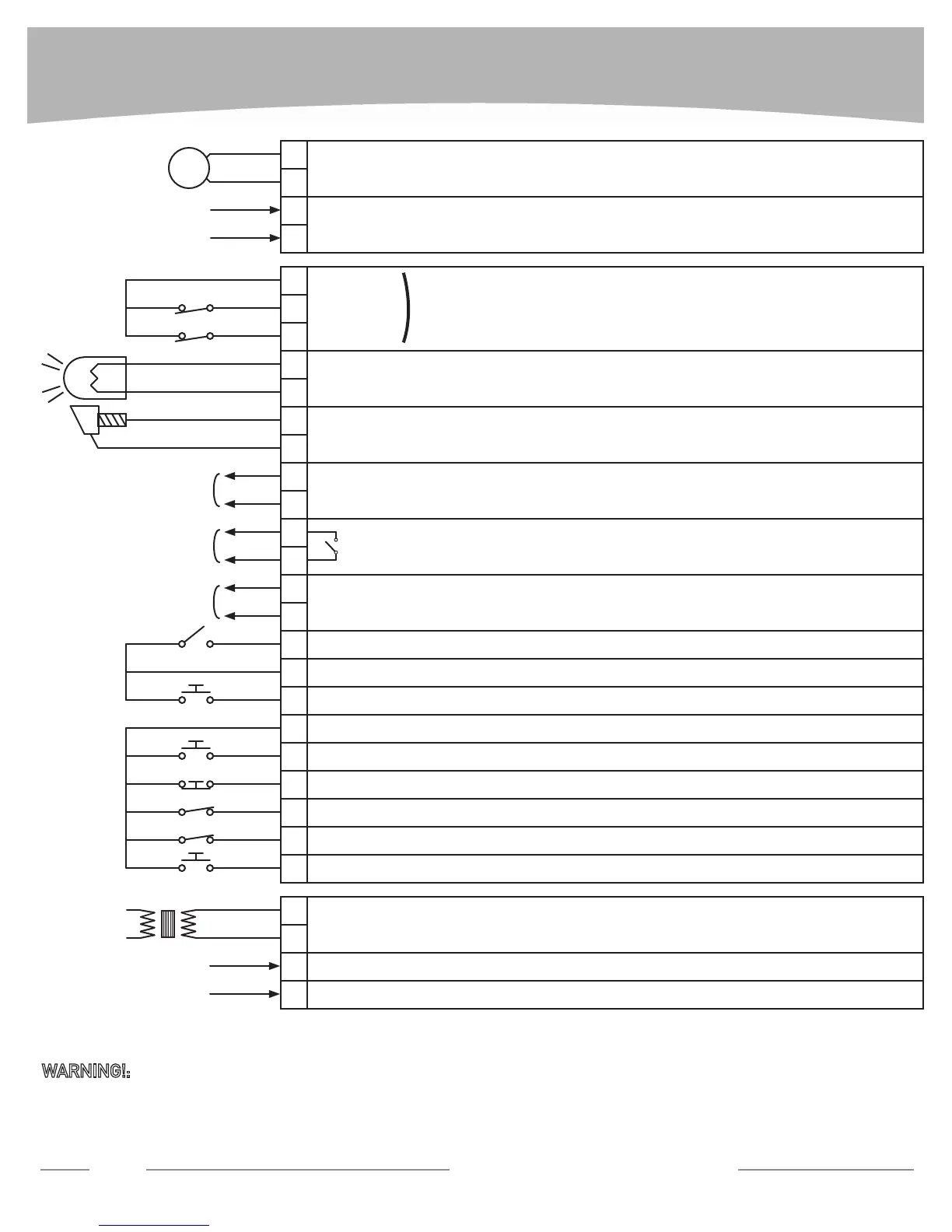
WIRING DIAGRAM
16
Technical Support: 1-877-995-8155
MOTOR CONNECTION
TRANSFORMER SECONDARY
TRANSFORMER PRIMARY
STROBE LIGHT CONNECTION
ANTENNA CONNECTION
UL ALARM: the contact closes after 2 consecutive obstruction detections with no limit switch activation.
Can be reset by opening the stop contact or switching off the power supply.
PHOTOBEAM TEST:
it requires different wiring to be used , please refer to instruction manual.
PHOTOBEAM:
it stops the gate when opened, when closed back continues opening (if gate opening) or reverses
(if gate closing).
SAFETY EDGE:
it stops, reverses and halts the gate when engaged. Further command needed to move the gate.
OPEN:
itopensthegatewhenclosed(eg.freeexitlooportelephone entry contact).
NEUTRAL (WHITE)
LINE (BLACK)
PARTIAL OPENING:
it open the gate 3’.
START/CLOSE:
it opens-closes-stops (START) or always closes (CLOSE) the gate depending on the logic setting
(default is START).
STOP & RESET:
it stops the gate and UL ALARM when opened.
COMMON
COMMON
(-)
24 Vac POWER SUPPLY TO ACCESSORIES
(+)
(-)
24 Vac FAIL SAFE POWER SUPPLY:
it requires different wiring to be used , please refer to
instruction manual.
(+)
BLACK
LIMIT SWITCH CONNECTIONRED
BROWN
1
5
13
9
17
23
31
2
6
14
10
18
24
32
3
7
15
21
11
19
25
33
4
8
16
22
12
20
26
34
M
BLUE
RED
COM
FAULT
N.C.
N.O.
N.C.
N.C.
N.C.
N.C.
N.O.
N.O.
N.O.
SWO
PED
START
PHOT
OPEN
ANTENNA
SHIELD
24 Vac/dc
(180mAmax)
24 Vac/dc Vsafe
(180mAmax)
UL ALARM
N.O.
SWC
COM
COM
STOP
BAR
24Vdc/25Wmax
120 Vac power input
WARNING!:
when the UL ALARM is active (#14-15 open) the board does not respond to any command. To make the board opera-
tional again, reset the board (open and close STOP terminal #21-23 or turn the power off and back on).
 Loading...