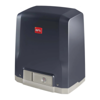
OPERATOR AND RACK INSTALLATION
6
Technical Support: 1-877-995-8155
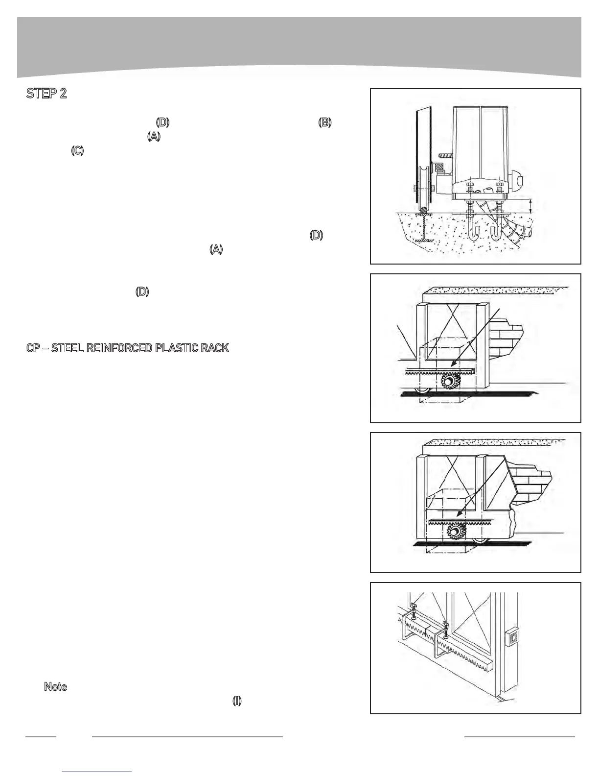
STEP 2
Position provided nuts • (D) and height adjustment plates (B) on
the anchoring hooks
(A) at least 1” higher than the template
plate (C) (Fig. 3).
This clearance is very important, in case the V-tracks sags, hav-
ing no clearance prevents any future adjustment, the pinion will
bear part of the weight of the gate, leading to wear of the rack
and pinion teeth and possible damage to pinion shaft and bear-
ings.
Level height adjustment plates using the 4 lower nuts • (D).
Remove the cover of the operator • (A) and place it on the two
height adjustment plates. Slide it into its nal operating position
(pinion close to the gate).
Use provided nuts •
(D) to secure the operator.
Disengage the gate by turning the release knob clock-wise until •
a “click” is heard.
CP – STEEL REINFORCED PLASTIC RACK
Start with gate in closed position.
1.
Put one end of rack section on the sprocket. Make it level and 2.
mark on the gate the center of the slot (Fig. 4).
Manually slide the gate so that the mark on the gate is reach-
3.
able. Drill a hole on the gate and connect the rack to the gate us-
ing a self tapping screw (not provided). Make sure that the screw
is centered in the slot for future adjustment.
Put the rack on the pinion and slide the gate so that the other 4.
end of the rack section is on the pinion, mark the center of the
slot on the gate (Fig. 5).
Manually slide the gate, drill a hole on the mark and connect the 5.
second end of the rack to the gate using a self tapping screw
(not provided).
The rst section of the rack is positioned, use a third screw to 6.
secure the section (at least 3 screws for section have to be used).
Repeat steps from 2 to 6 to position other sections of the rack
7.
until proper length is reached.
It is suggested to use an additional section of the rack clamped
8.
on the section which is already connected to the gate and on the
section to be connected to grant proper teeth pitch between dif-
ferent section (Fig. 6).
If needed, cut the last section to meet gate length. 9.
Note: rack length must be longer than actual travel of the gate
to accommodate limit switch brackets
(I)(1’6”approx.oneach
side).
FIG. 4
FIG. 6
FIG. 4
Mark and bolt
FIG. 5
Mark and bolt
FIG. 3
Min 1”
 Loading...