Radio Interfer
ence
Check the following if radio interference is encountered:
• Station tuning
• Mechanical damage to antenna structure
• Supply voltage terminal Rad_On for antenna amplifiers in
diversity module
• Antenna connector at diversity module
• Ground connection of diversity module with mounting screws
• Antenna connector at radio or navigation system
The E93 supports the following concepts for minimizing interfer-
ence in the reception of AM and FM stations:
• Ground connection of rear lid via read lid hinge with integrated
ground straps
• Ground connection of hinges on left and right of body
• Low-noise AM and FM antenna amplifiers with direct ground
screw connection
E93 Complete Vehicle Workbook
33
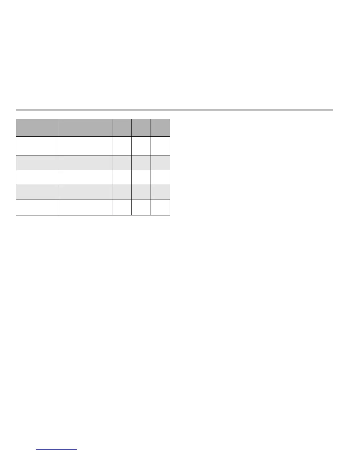
Operating Mode Remark
“Us”
min
“Us”
typical
“Us”
max
FM1/AM
AM reception, diversity off
----
0 V
0.5 V due
to ground
offset
DIV
Diversity mode
1.5 V
2.5 V 3.5 V
Diagnostic mode
AM/FM diagnosis, AM
amplifier off
4.0 V
5.0 V 6.5 V
Switching pulse
Diagnosis, FM antenna
switching
7.5 V
8.5 V 14 V
Diagnostic result
not OK
Diagnosis output short circuit
proof, Us is switched across
200 Ohms to ground
0 V
0.5 V 2 V

 Loading...