The two Low-g sensors (3) have a small measuring range of 0-2 g
and can therefore detect small accelerations and decelerations with
great accuracy. For example, when the vehicle skids sideways off
the road surface and buries itself with its wheels in soft ground.
The sensors provide a voltage as measured variable. This voltage
is a measure for the acceleration and is converted directly into
digital signals in the sensor. The digital values are sent to the
processor for evaluation.
The processor evaluates the signals from the longitudinal and
transverse acceleration sensors and the two Low-g sensors.
The rotation rate sensor is also included in the calculation.
The results are compared with the stored algorithm. When
the processor detects that a rollover is imminent, it sends two
telegrams within a defined timeframe to the ROC control unit
with the instruction to trigger the actuators.
Triggering the Rollbars
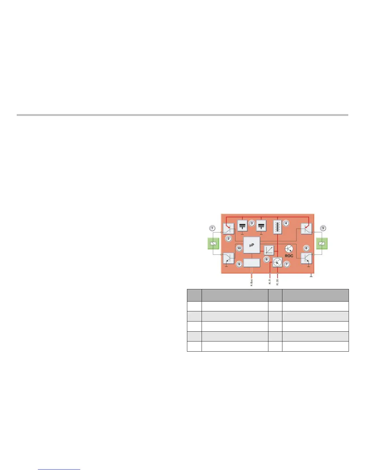
The ROC control unit is supplied with load current via terminal 30.
Terminal R ON is applied as the switching signal and enables the
power circuit-breaker (7). In this way, the voltage regulator (8), the
microprocessor (10) and the switching controller (4) are supplied
with voltage. The switching controller transforms the voltage into
35 V and charges up the two firing capacitors (3).
When the processor in the crash safety module detects an immi-
nent rollover, it sends two telegrams within a defined time window
via the K-bus.
The first telegram instructs the ROC control unit to make itself
ready for firing (arming telegram). The ROC control unit incorpo-
rates two firing capacitors (3) connected in parallel for providing the
firing energy. Each actuator has one high-side and one low-side
power circuit-breaker.
The second telegram contains the firing command (firing telegram).
The low-side power circuit-breakers (6) are connected to ground
and the two high-side power circuit breakers (2) are switched
through. The ROC control unit now discharges the two firing
capacitors and the two actuators are supplied with voltage.
During normal operation, the rollbars are inserted in the cassettes
in the partition module. They are pre-tensioned in the direction of
their extension by a spring and held in place by a lock on the actua-
tor.
The ROC control unit activates the two actuators via the output
stages. Each actuator consists of a single-acting solenoid with
a lock for disengaging and engaging its rollbar. The solenoid
actuates the lock and releases the spring-loaded rollbar.
46
E93 Complete Vehicle Workbook
Index Explanation Index Explanation
1
Actuator, left
6
Low side power circuit breaker
2
High side power circuit breaker
7
Power circuit breaker
3
Firing capacitors
8
Voltage regulator
4
Switching controller
9
K-bus interface
5
Actuator, right
10
Microprocessor

 Loading...