Electronic Thermostat Installation | 13EP Series
8733953041 (2019/01)
EP Series
• L.E.D. FAULT INDICATION: Two L.E.D.
indicators are provided:
Green: Power L.E.D. indicates 18-30 VAC
present on board.
Red: Fault indicator with the following blink
codes;
1 - High Pressure Lockout
2 - Low Pressure Lockout
3 - Freeze Sensor Lockout
4 - Condensate Overflow
5 - Brownout
• INTELLIGENT RESET: If a fault condition is
initiated, the 5 minute delay on break time
period is initiated and the unit will restart after
these delays expire. During this period the
fault LED will indicate the cause of the fault. If
the fault condition still exists or occurs 2 or 4
times (depending on 2 or 4 setting for Lockout
dip switch) before 60 minutes, the unit will go
into a hard lockout and requires a manual
lockout reset. A single condensate overflow
fault will cause the unit to go into a hard
lockout immediately, and will require a manual
lockout reset.
• LOCKOUT RESET: A hard lockout can be reset
by turning the unit thermostat off and then
back on when the “RESET” dip switch is set to
“Y” or by shutting off unit power at the circuit
breaker when the “RESET” dip switch is set to
“R”.
ELECTRONIC THERMOSTAT
INSTALLATION
Position the thermostat subbase against the wall
so that it is level and the thermostat wires
protrude through the middle of the subbase. Mark
the position of the subbase mounting holes and
drill holes with a 3/16-inch bit. Install supplied
anchors and secure base to the wall. Thermostat
wire must be 8-conductor, 18-AWG wire. Strip the
wires back 1/4-inch (longer strip lengths may
cause shorts) and insert the thermostat wires into
the connector as shown. Tighten the screws to
ensure secure connections. The thermostat has
the same type connectors, requiring the same
wiring. See instructions in the thermostat for
detailed installation and operation information
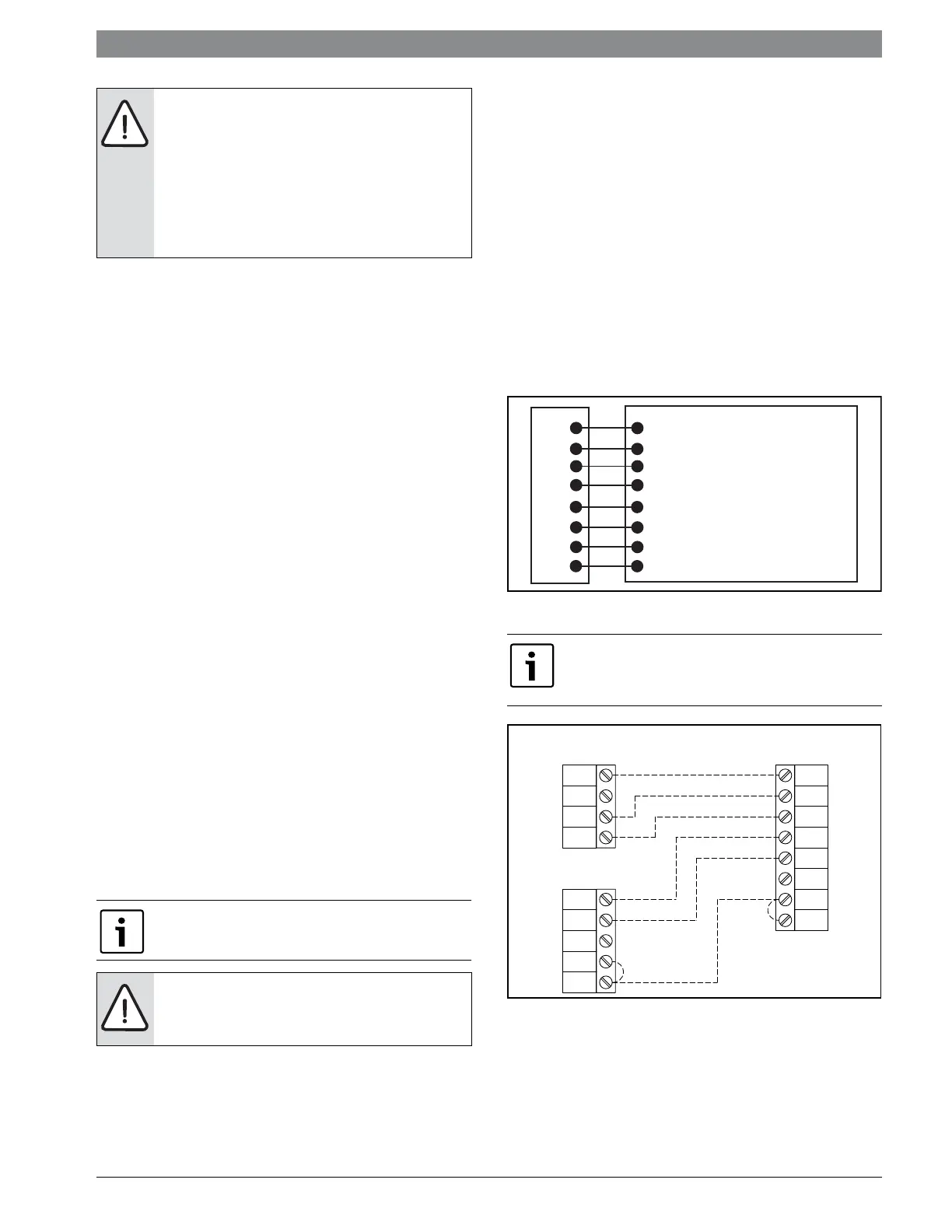
Figure # 15 Thermostat Wiring
Figure # 16
NOTE: If unit is employing a fresh water
system (no anti-freeze protection), it is
extremely important to have the Freeze1
R42 resistor set to 26°F in order to shut
down the unit at the appropriate leaving
water temperature and protect your heat
pump from freezing if a freeze sensor is
included.
The blower motor will remain active during a
lockout condition.
NOTE: Always check incoming line
voltage power supply and secondary
control voltage for adequacy
NOTE: When using a 2-cool, 3-heat thermostat
W1 and W2/EM must be connected together via
a jumper. (Figure#16)
24VAC (Hot)
24VAC (Common)
Compressor (1st Stage)
Compressor (2nd Stage)
Auxiliary Heat
Reversing Valve
Blower Relay
System Monitor
R
C
Y1
Y2
w
O
G
L
MICROPROCESSOR CONTROLLER
THERMOSTAT CONNECTION
THERMOSTAT
PACKAGED
HEAT PUMP
Y
G
C
O
R
Y
G
B
R
W2
C
O
E
B
W1
W2
 Loading...