CONDENSATE DRAIN | 7EP Series
8733953041 (2019/01)
EP Series
CONDENSATE DRAIN
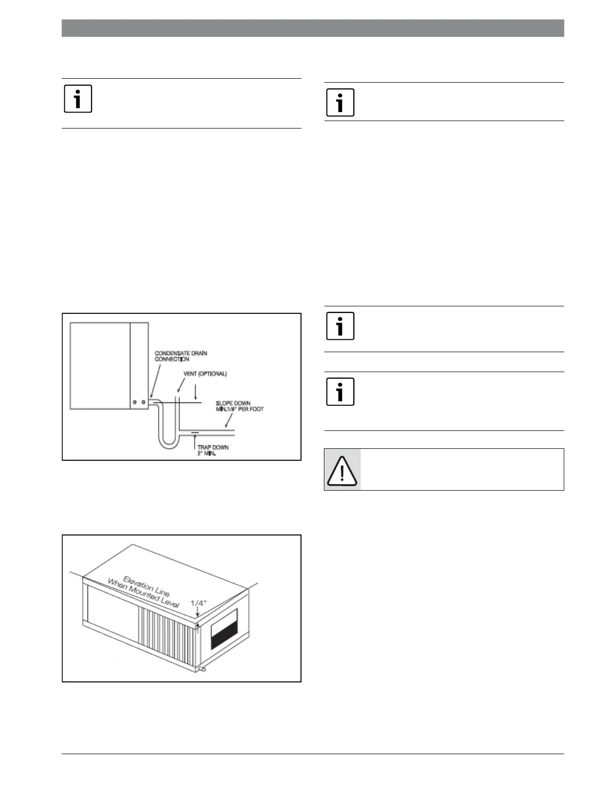
A drain line must be connected to the heat pump
and pitched away from the unit a minimum of 1/8”
per foot to allow the condensate to flow away from
the unit.
This connection must be in conformance with local
plumbing codes. A trap must be installed in the
condensate line to insure free condensate flow.
(Heat Pumps are not internally trapped).
A vertical air vent is sometimes required to avoid
air pockets.(See Figure #8).
The length of the trap depends on the amount of
positive or negative pressure on the drain pan. A
second trap must not be included.
Figure # 8
The horizontal unit should be pitched
approximately 1/4” towards the drain in both
directions, to facilitate condensate removal. (See
Figure #9)
Figure # 9
DUCT SYSTEM
A supply air outlet collar and return air duct flange
are provided on all units to facilitate duct
connections. Fold the duct flange outwards along
the perforated line. Refer to unit Dimensional
Drawings for physical dimensions of the collar and
flange. (Pg#33 through Pg#34)
A flexible connector is recommended for supply
and return air duct connections on metal duct
systems. All metal ducting should be insulated
with a minimum of one inch duct insulation to
avoid heat loss or gain and prevent condensate
forming during the cooling operation.
If the unit will be installed in a new installation
which includes new duct work, the installation
should be designed using current ASHRAE
procedures for duct sizing.
If the unit is to be connected to existing duct work,
a check should be made to assure that the duct
system has the capacity to handle the air required
for the unit application. If the duct system is too
small, larger duct work should be installed. Check
for existing leaks and repair.
The duct system and all diffusers should be sized
to handle the designed air flow quietly. To
maximize sound attenuation of the unit blower, the
supply and return air plenums should be insulated.
There should be no direct straight air path thru the
return air grille into the heat pump.
If equipped with float style condensate
overflow switch, final adjustment must be
made in the field.
Supply air duct and return air duct flanges are
shipped unfolded with unit.
NOTE: Application of the unit to no insulated
duct work is not recommended as the unit’s
performance will be adversely affected.
NOTE: The factory provided air filter must be
removed when using a filter back return air grill.
The factory filter should be left in place on a free
return system
NOTE: Do not connect discharge ducts
directly to the blower outlet.
 Loading...