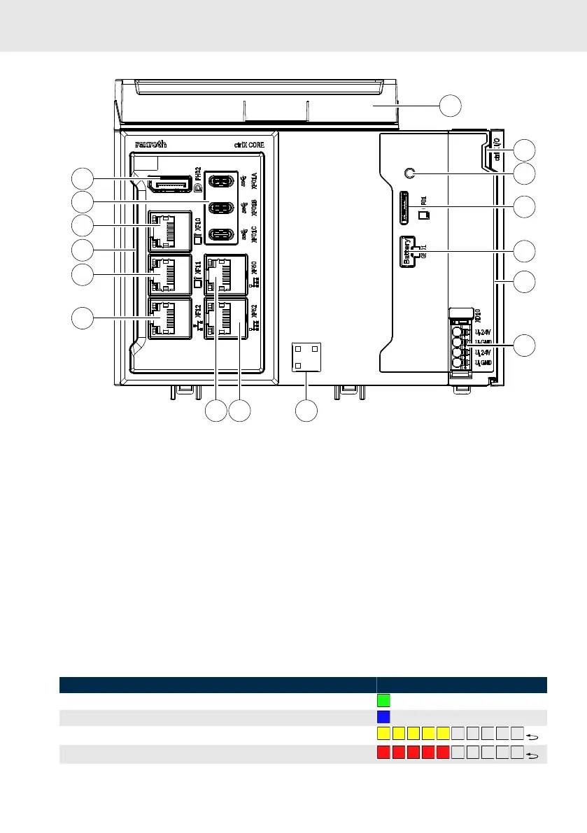
Fig. 16: Device view of the CORE
PLUS
①
Fan unit
②
Device status LED
③
Pushbutton
④
SD card slot
⑤
Battery case
⑥
EtherCAT local bus interface
⑦
Voltage supply
⑧
QR code (references to the Bosch
Rexroth product catalog)
⑨⑩
Field bus master (EtherCAT)
⑪⑫⑭
HMI engineering port
⑬
ctrlX CORE status LED
⑮
3 × USB 3.1 type C
⑯
Display port
12.2 Status displays
To diagnose errors, there are two status displays on the ctrlX CORE
PLUS
: The ctrlX CORE status LED and
the device status LED
The following functions are assigned to the ctlrX CORE status LED when the system firmware is running:
Table 9: Status LED
State Color
Control in "Run" state Green
Control in "Stop" state Blue
Warning in the ctrlX CORE Runtime Flashing yellow
Errors (F0 – F7
①
) in the ctrlX CORE Runtime
Flashing red

 Loading...