Page 14 User Guide English
Installation and Operating Guide pro.Bose.com
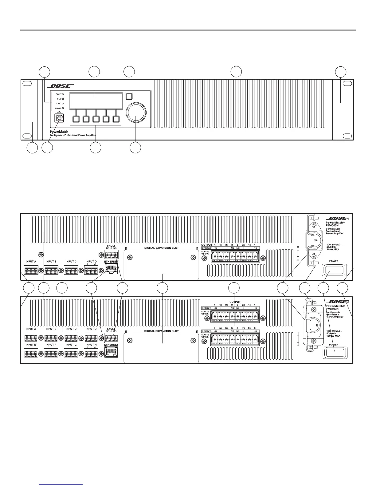
Controls, Display, and Connectors
Figures 1 and 2 detail the various elements found on the front and rear panels of PowerMatch amplifiers.
Figure 1. Front Panel View
1. LED Indicators
2. LCD Screen
3. Navigation Soft Key
4. Rotary Encoder
5. Menu Soft Keys (1-5)
6. USB connector
7. Front airflow intake vents
8. Front rack-mount ears
Figure 2. 4-channel and 8-channel Rear Panel Views
9. Analog Input connectors
10. Fault Notification Output
11. Ethernet RJ-45 network connector
(Network versions only)
12. Rear airflow exhaust vents
13. Digital expansion card slot cover
14. Loudspeaker output connectors
15. AC Mains receptacle
16. AC Mains retention clip
17. Power Switch/Resettable Circuit Breaker
18. Rear rack-mount support tabs
3
1
2
456
7
8
8
9 141112 15 17131018 1816
 Loading...