3 - 58
Main parts
Application of Assembly
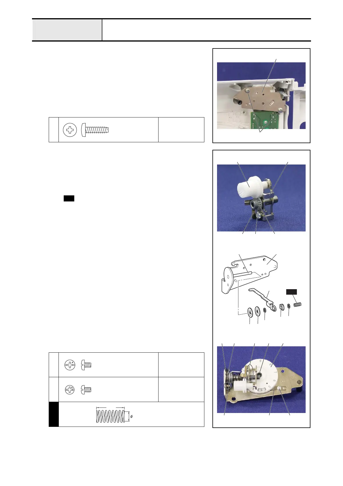
2-14Attachment of Thread tension holder A assy
1. Set the thread guide A assy. 1 to the front cover assy. with the 2 screws
1.
1
Torque
0.78 – 1.18 N·m
1
1
Taptite, Bind B
M4X14
2-14-1Assembly of Thread tension holder A assy
1. Insert the thread tension adjusting gear 2 into the shaft of the thread
tension plate assy. 1, and then set the thread tension adjusting screw 3.
2. Set the adjusting screw spring plate 4 to the thread tension plate assy. 1
with the screw 1.
3. Insert the tension disc A 7, the tension disc B 8, the washer 9, the
thread release plate 0, the tension disc washer A, the washer B and the
spring in this order into the shaft 6 of the thread tension holder A
assy. 5.
*Key point
• Check that align the notch part of the tension disc A 7 and the
tension disc B 8 with the protrusion C of the thread tension
holder A assy..
4. Engage the groove part E of the thread tension dial D with the protrusion
of the thread tension plate assy. 1, and insert the thread tension adjusting
screw 3 into the shaft, and then set the thread tension dial D to the thread
tension holder A assy. with the tension dial shaft F.
*Key point
• Set the tension dial shaft F to the thread tension dial D in the
state that the [9] of the thread tension dial D is the upper side.
5. Set the notch spring G to the thread tension holder A assy. 5 with the
screw 2.
*Key point
• Attach the end of the notch spring G to the lower side of the
thread tension dial D.
• Check that the boss part of the thread tension holder A assy.
engaged with the positioning hole of the notch spring G.
1
Torque
0.78 – 1.18 N·m
2
Torque
0.78 – 1.18 N·m
S01
0
6
5
7
8
9
A
B
S01
1
4
2
3
1
C G
7 8 EDF
2
S01
Screw, Bind
M3X4
Screw, Pan
M3X4
Spring
XE3014***
7.6
17.0
 Loading...