3 - 90
Needle-presser module
Application of Assembly
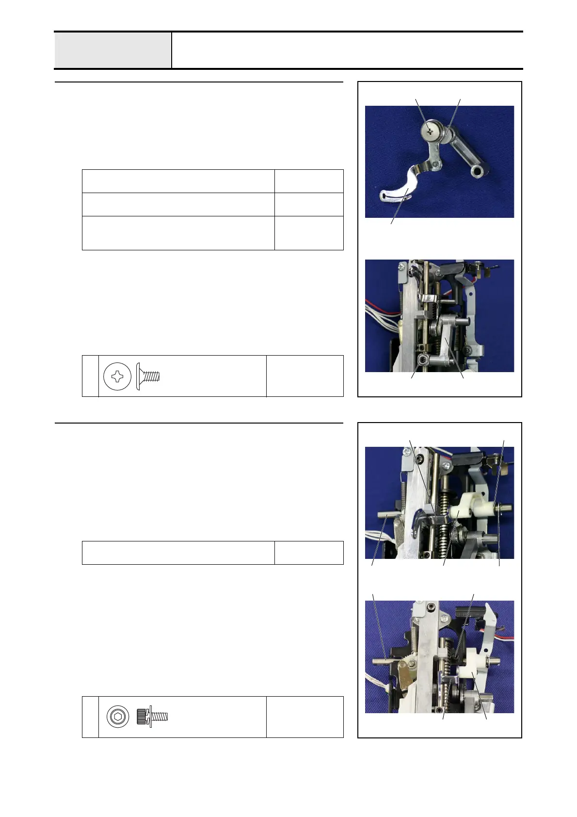
17 Attachment of Needle bar crank rod assy
1. Set the thread take-up lever 1 to the needle bar crank rod assy. 2 with the
screw 1.
*Key point
• The screw 1 is reverse threaded.
2. Set the needle bar crank rod assy. 2 to the needle bar block 3.
Apply EPNOC AP (N) 0 to the shaft of the needle
bar crank.
Small amount
XC8387***
Apply EPNOC AP (N) 0 to the shaft of the thread
take-up lever.
Small amount
XC8387***
Apply EPNOC AP (N) 0 to the thread take-up
lever attachment face (left screw attachment face)
of the needle bar crank.
Small amount
XC8387***
1
Torque
1.18 – 1.57 N·m
2
1
1
3
2
Screw, Flat
SM3.57L
18 Attachment of Thread take-up lever link
1. Attach the retaining ring E5 to the take-up support shaft 1.
2. Set the base holder assy. as shown in the right figure, and then insert the
take-up support shaft 1 into the washer, spring 2, the thread take-up
lever link 3 and the base holder assy. from the right side, and then attach it
with the screw 1.
*Key point
• Insert the shaft of the thread take-up lever 4 into the thread
take-up lever link 3.
Apply EPNOC AP (N) 0 to the all around the take-
up support shaft hole.
Small amount
XC8387***
1
Torque
1.18 – 1.57 N·m
2
1
3
Retaining ring E5
1
3
1
4
4
Screw
3X8
 Loading...