&.ASSEMBLY
6.ASSEMBLY
I
Assemble each part in order
of
the numbers.
Apply grease to the required places when reassembling the parts and once every two years.
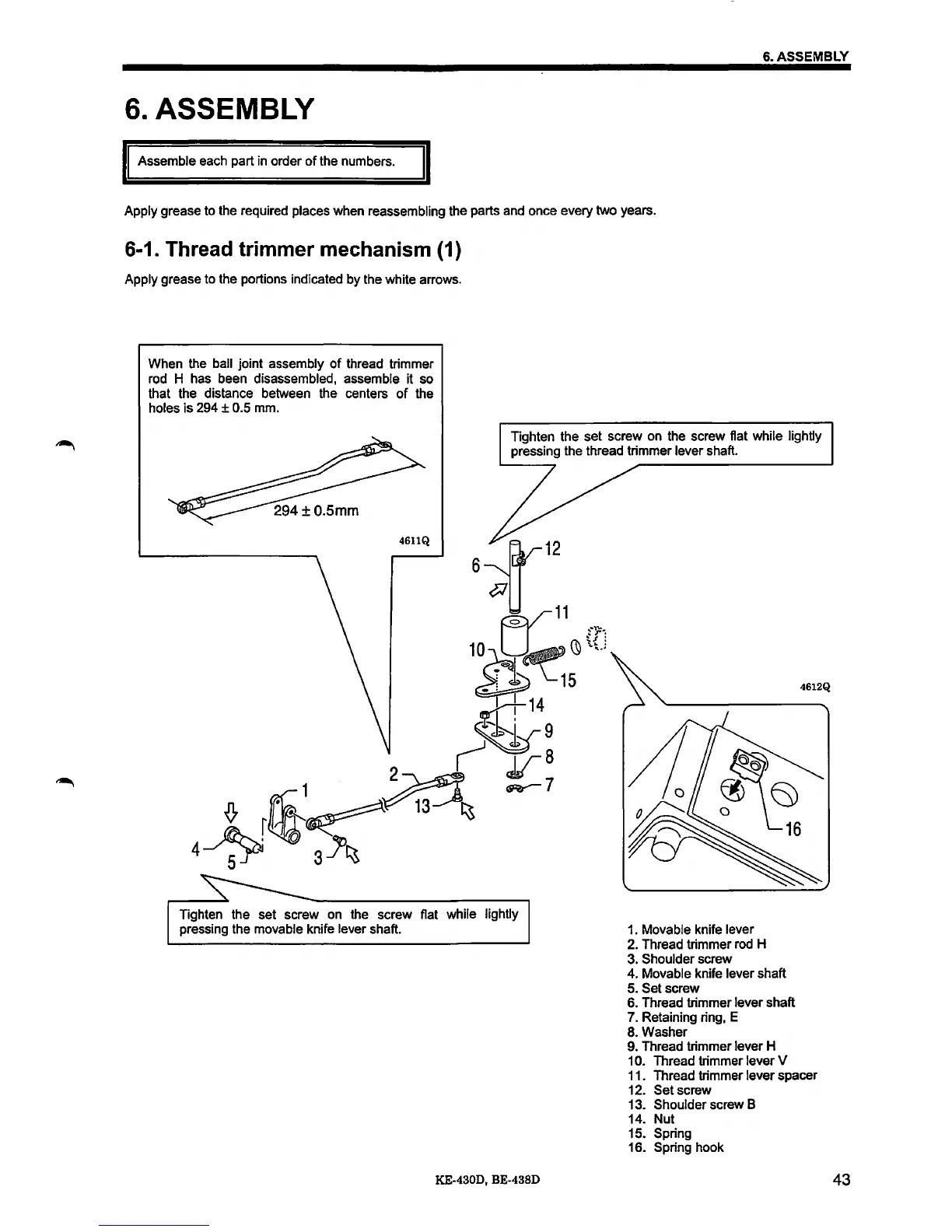
6-1. Thread trimmer mechanism (1)
Apply grease to the portions indicated by the white arrows.
When the
ball joint assembly
of
thread trimmer
rod H has been disassembled, assemble it so
that the distance between the centers
of
the
holes is
294 ± 0.5 mm.
Tighten the set screw on the screw flat while lightly
pressing the thread trimmer lever shaft.
Tighten the set screw on the screw flat while lightly
pressing the movable knife lever shaft.
KE-4300, BE-4380
1. Movable knife lever
2.
Thread trimmer rod H
3. Shoulder screw
4. Movable knife lever shaft
5. Set screw
6. Thread trimmer lever shaft
7.
Retaining ring, E
8. Washer
9.
Thread trimmer lever H
1 0. Thread trimmer lever V
11.
Thread trimmer lever spacer
12. Set screw
13.
Shoulder screw B
14. Nut
15.
Spring
16. Spring hook
43
 Loading...