POWER CONSIDERATIONS:
In general, if your BDP-2 has a three prong ground-
ed line cord you can reduce the possibility of local
ground loops which could cause hum or noise in
the system by plugging its line cord into the same
wall outlet next to the power amp and other
equipment in your system.
FUSES & ELECTRICAL SAFETY:
The BDP-2 contains two glass fuses (5x20mm cy-
lindrical), one for the standby power supply and
one for the main linear power supply. IF it should
become necessary to replace either of these
fuses we recommend that you seek the assistance
of qualied service personnel. If you decide to
change the fuse yourself we advise the following:
1st) Turn off the BDP-2
2nd) Disconnect ALL cables from the rear of the
BDP-2, especially the power cord.
3rd) Remove all 10 screws securing the top
cover to the chassis and remove the top
cover.
4th) Locate the 5x20mm glass fuses on the
power supply board at the rear left corner
of the unit (near the IEC power inlet). Re-
place blown fuses only with the same type
and value. All fuses are rated 250V and
are slow acting (time lag) types. Refer to
the Fuse label inside the unit for the exact
replacement values.
5th) Replace the top panel and all screws and
reconnect all cables before plugging in the
unit and turning it back on.
MAINS
VOLTAGE
STANDBY
FUSE
MAIN FUSE
mA
Part
Number
mA
Part
Number
100 250 218.250 500 218.500
120
250
218.250 500 218.500
200
315
218.315 315 218.315
230
240
315
218.315 315 218.315
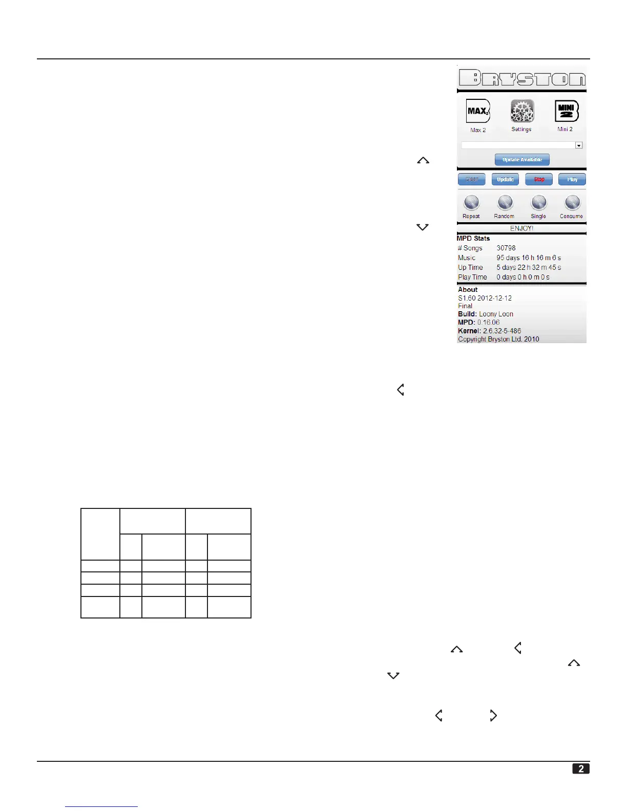
FIRMWARE UPDATES
BDP-2 firmware updates will periodically be avail-
able from Bryston. To install updates you will
have to have your BDP-2 connected, via its Ether-
net connection, to a router or computer with an
internet connection. Enter bryston-BDP-2.local
in the address bar of your computers web browser
to connect to the BDP-2 and then click updata
available.(refer to the screen shot at right)
To determine which
version of firmware is
running on your BDP-
2, use the front panel
navigation keys to go
back to the top of the
BDP-2’s menu. Then
push the UP key
again to display the
firmware version num-
ber and its date on the
2nd line of the display.
Press the DOWN ar-
row navigation button
to display the units IP
address (this would be
useful if Bonjour or
a similar service dis-
covery protocol isn’t
installed on your per-
sonal computer and you
have to use the actual
IP address instead of the name bryston-BDP-2.lo-
cal ). With the IP address displayed, pressing the
LEFT button will display the units MAC address.
REMOTE TRIGGER
The TRIGGER IN and OUT connectors (3.5mm
2-conductor phone jacks) allow for implemen-
tation of a hard wired remote power ON/OFF
control. The INput can accept any DC voltage
between 3 and 12 volts DC and the input is polor-
ity insensitive as the input voltage is bridge recti-
fied. A minumum control voltage of 3Vdc @ 1mA
is required to trigger the unit ON. As soon as the
BDP-2 has powered up, whatever control voltage
is present at the IN jack will be connected to the
Trigger OUT jack via an isolated to allows for daisy
chaining several pieces of equipment to a single
remote control voltage signal .
DISPLAY BRIGHTNESS & AUTO SHUTOFF
To bring up a brightness and auto shutoff time de-
lay menu, press the UP and LEFT menu navi-
gation buttons in rapid succession. Use the UP
and DOWN buttons to switch between setting
the brightness (from 1 to 4) and the time delay
(from always on, 10 seconds, 1 minute, 5 minutes,
etc.) using the LEFT & RIGHT buttons. The
menu will dissappear approx. 10 seconds after the
last button press
SYSTEM CONFIGURATIONS:
BDP-2 DIGITAL PLAYER
[contd. on pg 5]
 Loading...