DC10 E, DC20 E
DISASSEMBLING
12
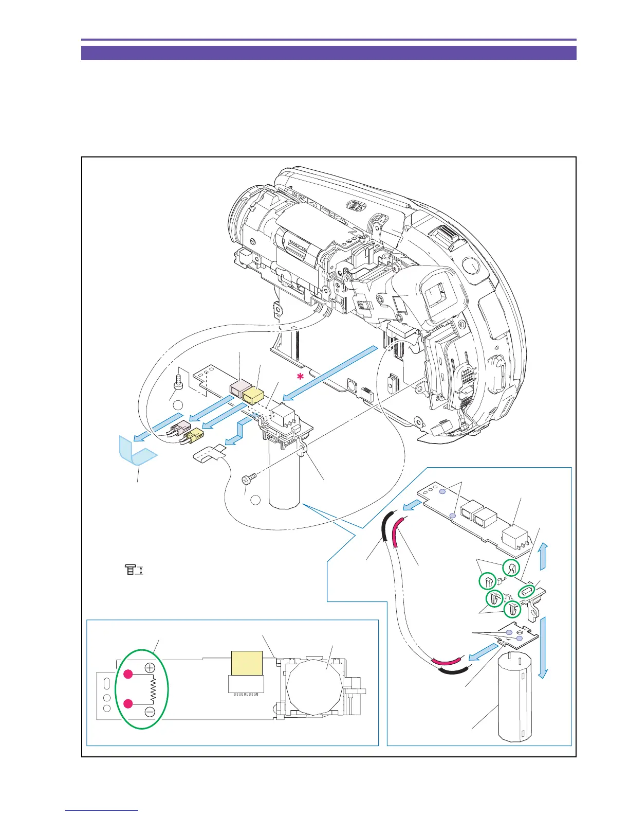
1-6 Separation of Flash PCB ASS'Y (DC20 E only)
Note : After separating the Rear Cover Unit, be sure to discharge the Main Capacitor. (A high voltage is present on
the circuit. Be careful not to receive electric shock or cause accidental contact with other parts.)
(1) Peel off the UL Tape. Remove two screws (a × 2), disconnect the CN500, the CN501, and the CN502, and then detach the Flash
PCB Ass'y.
(2) Disengage three claws A and two claws B, and unsolder part α (two points) and part β (two points) , and detach the FLASH PCB,
the Flash PCB Holder, the Capacitor PCB, the Main Capacitor, and the Condenser Wire.
Fig. 9
Metal
M1.7
a
2.5mm
Note
(1)
(1)
Flash PCB Ass'y
FLASH PCB
(1) - a
(1) - a
CN500
Main Capacitor
CAPACITOR PCB
Main Capacitor
CN501
CN502
FLASH PCB
Flash PCB
Holder
Discharge resistance : Approx.1KΩSW
Discharge point
(2)
(2)
(2)
(2)
Solder β
Condenser
Wire +
(Red)
Condenser
Wire −
(Black)
Claws A
Claw A
Claws B
Solder α
(1)
UL Tape
(9 × 20mm)

 Loading...