DC10 E, DC20 E
DISASSEMBLING
15
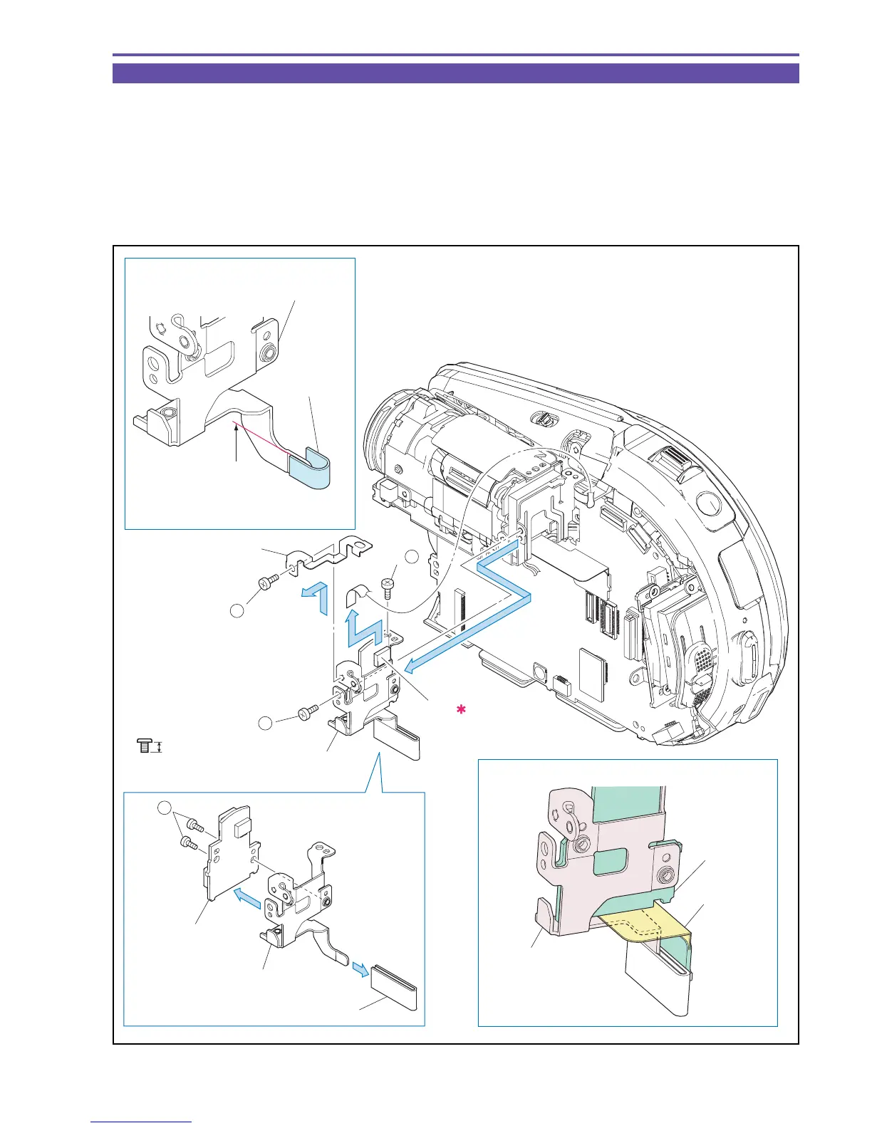
1-8 Separation of GYRO PCB
(1) Remove one screw (a × 1), and detach the GYRO GND Plate.
(2) Remove two screws (a × 2), disconnect the CN1601, and detach the GYRO PCB Section.
(3) Remove two screws (a × 2), and detach the GYRO PCB.
(4) Detach the CCD Connector Sheet from the GYRO Holder.
<Note on Reassembling>
(1) Attach the CCD Connector Sheet as shown in the figure below.
(2) Attach the GYRO PCB Section as shown in the figure below.
Fig. 12
Metal
M1.7
a
2.5mm
Note on Reassembling (1)
Note on Reassembling (2)
(3)
(4)
(3) - a
GYRO PCB
GYRO GND Plate
GYRO PCB
Section
GYRO Holder
CCD Connecter Sheet
(2)
(1)
CN1601
(2) - a
(1) - a
(2) - a
(2)
GYRO PCB
GYRO Holder
GYRO Holder
CCD FPC
CCD
Connecter
Sheet
Bend it and stick it so that the face
and the back have the same length.
Insert the CCD FPC
between the GYRO PCB
and the GYRO Holder.
Attachment
reference

 Loading...