3-7
Part 3: Adjustment
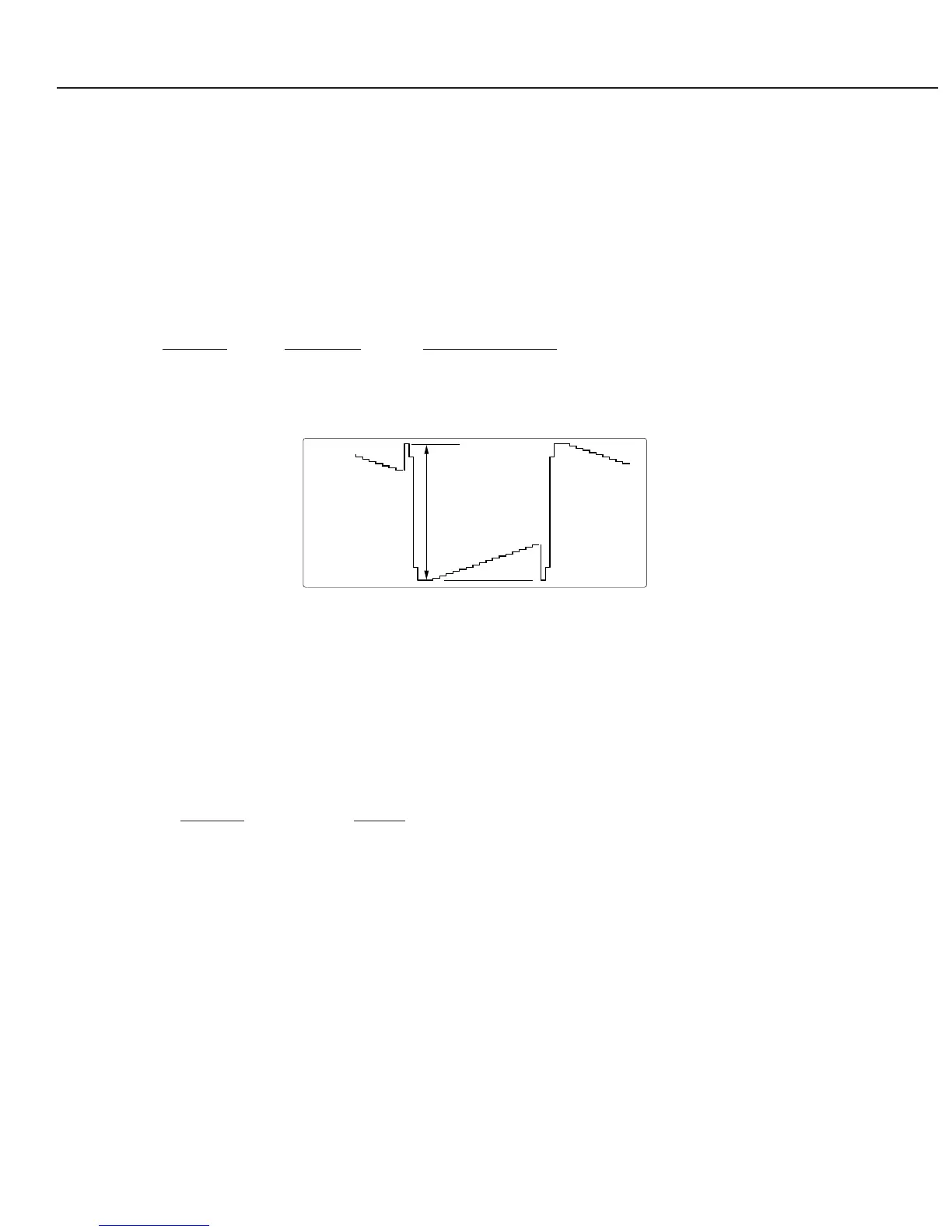
2.5 Signal Level Adjustment
Measuring equipment ............Oscilloscope
Input mode ...........................Computer
Input signal ...........................16-step gray scale
Enter the service mode.
Adjust part A of signal waveform at each test point to the following value with the
VOLUME +/- button.
Item No. Test point
Adjustment value
10 TP-R1 10V ± 0.1V p-p
11 TP-G1 10V ± 0.1V p-p
12 TP-B1 10V ± 0.1V p-p
Fig. 3-4
2.6 Flicker Adjustment
Input mode ...........................Computer
Input signal ...........................1-dot line computer signal
Enter the service mode.
Minimize flicker on each color screen with the VOLUME +/- button.
Item No. Screen
19 Red screen
20 Green screen
21 Blue screen
 Loading...