11
ENG
easy/easy compact/easy split +030220791 - rel. 3.2 - 13.07.2010
2.2 Electrical connections
Warnings:
• the electrical connections must only be completed by a quali ed
electrician;
• a power supply other than the type speci ed may seriously damage
the system;
• on easy split models supplied with plastic case, given the high
maximum power supply current (16 A), the unit may heat up: in this
case, make sure the maximum temperature allowed is not exceeded.
See the table of technical speci cations;
• separate as much as possible the probes and digital input signal
cables from the cables carrying inductive loads and power cables to
avoid possible electromagnetic disturbance. Never lay power cables
(including the electrical cables) and probe signal cables in the same
conduits. Do not install the probe cables in the immediate vicinity of
power devices (contactors, circuit breakers or similar);
• reduce the path of the probe and sensor cables as much as possible,
and avoid spiral paths that enclose power devices. The probes must
be connected using shielded cables (minimum cross-section of each
wire: 0.5 mm
2
);
• avoid direct contact with internal electronic components;
• connection errors (and connections other than those indicated in this
manual) may involve danger to the safety of the users and cause faults
on the instruments and the components connected;
• t the unit with all the electromechanical safety devices required to
guarantee correct operation and the complete safety of the user.
Information:
• the probes can be installed up to a maximum distance of 30 m from
the controller (10 m for easy split). To extend the distance of the probes,
use cables with a minimum cross-section of 1 mm, shielded where
possible. In this case, the shield must be connected to the common of
the probe. Do not earth the other end of the shield (the sensor end);
• only use IP67 probes as end defrost probes; place the probes with the
vertical bulb upwards, so as to assist the drainage of any condensate.
The thermistor temperature probes (NTC or PTC) have no polarity, so
the order of connection of the ends is not important;
• use cable ends suitable for the corresponding terminals. Loosen each
screw and insert the cable ends, then tighten the screws. When the
operation is completed, slightly tug the cables to check they are
su ciently tight.
The connections of the inputs and outputs, depending on the models,
may be made:
• using traditional screw terminals;
• using plug-in terminals with screw cable connection blocks;
• using plug-in terminals with crimped cable connection blocks.
• using plug-in terminals, which signi cantly simplify the connection
of the instrument both during installation and maintenance. This also
avoids connection errors, as there are three connection blocks with a
di erent number of pins.
Connect the inputs and the outputs following the diagram shown on the
instrument label.
For the 12 Vac versions:
• if the power supply available is mains, a safety transformer is required
to ensure double insulation between the power supply and the very
low voltage electronics. If required, a fuse must be installed in series
with the primary (32 mAT for code TRA12VDE00). The transformer-
instrument connection must be as short as possible;
• if the power supply available is already low voltage, but not 12 Vac,
a suitable adapting transformer must be used: double insulation
between the primary and secondary and de nition for surge on the
primary to the appropriate level (2000 V for applications in industrial
environments.
• as double insulation cannot be guaranteed between the power supply
connectors and the relay outputs, only use loads powered at safety
extra low voltage (e ective rating up to 42 V).
The voltage supplied to these terminals (see the wiring diagrams) must
correspond, within the speci ed tolerances, to the value shown on
the instrument connection label. The insulation of the instrument, for
versions with mains power supply (230 Vac and 115 Vac), is reinforced.
The versions with 12 Vac/Vdc power supply, on the other hand, do not
feature such insulation.
For easy split:
Refer to the following wiring diagram;
• power supply L, N, PE: use cables with a suitable cross-section for the
load (2.5 mm
2
for current ratings up to 16 A and 4 mm
2
for current
ratings up to 24 A);
• load connection: terminate with 6.3 mm female spade contacts, cable
cross-section 2.5 mm
2
for current ratings up to 16 A;
• use:
– cables with max. operating temperature at least 90 °C
– spade terminals with max. operating temperature at least 100 °C
• internal jumpers for power supply to loads as per the previous point;
• probe and digital input connections with 0.5 to 1.5 mm
2
cables;
• terminal connection using speci ed cables.
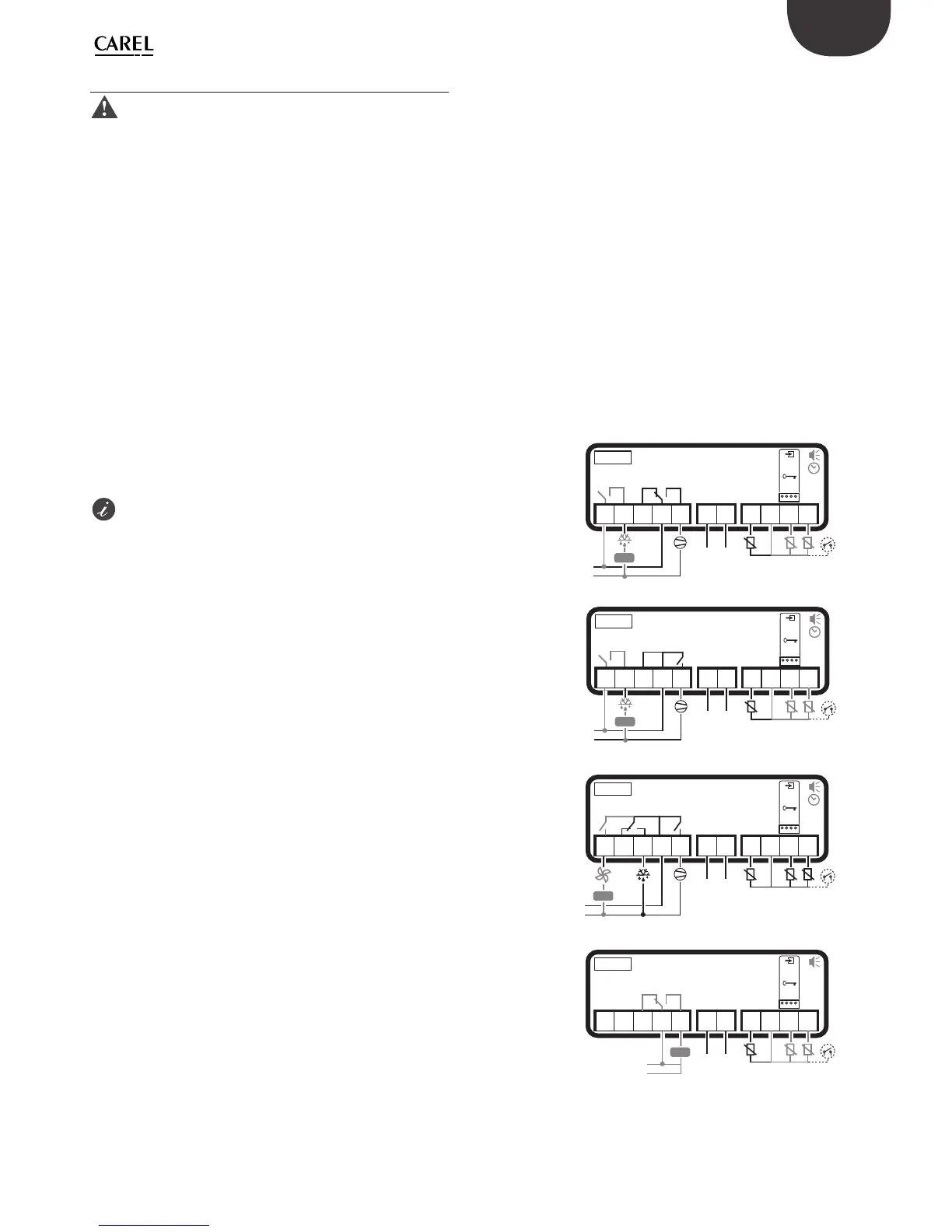
easy wiring diagrams
PJEZ(S, X)*
PJEZ(C, Y)*
1 2 3 4 5 6 7
9 10 118
L
N
L N
DEF. T.
DI / PROBE
AMB. T.
NTC/PTC
PROBES
or
SERIAL
CONV
PROG.
KEY
-10T50
1 2 3 4 5 6 7
9 10 118
L
N
L N
230Vac or
115 Vac or
12 Vac/Vdc
230Vac or
115 Vac or
12 Vac/Vdc
DEF. T.
DI / PROBE
AMB. T.
NTC/PTC
PROBES
or
or
SERIAL
CONV
PROG.
KEY
-10T50
AUX
or
AUX
PJEZ(M)*
1 2 3 4 5 6 7
9 10 118
L
N
L N
230Vac or
115 Vac or
12 Vac/Vdc
DEF. T.
DI / PROBE
AMB. T.
NTC/PTC
PROBES
or
SERIAL
CONV
PROG.
KEY
-10T50
AUX
PJEZ(S, X)*
Compressor
relay 2HP
1 2 3 4 5 6 7
9 10 118
L
N
L N
230Vac or
115 Vac or
12 Vac/Vdc
DEF. T.
DI / PROBE
AMB. T.
NTC/PTC
PROBES
or
SERIAL
CONV
PROG.
KEY
-10T50
or
AUX
Fig. 2.e
 Loading...