39
ENG
easy/easy compact/easy split +030220791 - rel. 3.2 - 13.07.2010
6. TECHNICAL SPECIFICATIONS
6.1 easy technical speci cations
power supply (*) 230 Vac +10 /-15% 50/60 Hz;
115 Vac +10 /-15% 50/60 Hz
12 Vac 10/-15 %, 50/60 Hz class 2
12 Vdc (11…16 Vdc) class 2
rated power 1.5 VA
inputs (*) NTC or PTC probes, 1 or 3 inputs. Digital input as
alternative to third probe
relay outputs (*) 2 HP relay UL: 12 A Res. 12 FLA 72 LRA, 240 Vac (***)
UL: 12 A Res. 10 FLA 60 LRA, 240 Vac (****)
EN60730-1: 10(10) A 250 Vac(**)
16 A relay UL: 12 A Res. 5FLA, 30LRA 250 Vac, C300
EN60730-1: 12(2) A NO/NC, 10(4) A no 60
°C NO, 2(2) A CO, 250 Vac
8 A relay UL: 8 A Res. 2 FLA 12 LRA, 250 Vac C300
EN60730-1: 8(4) A NO, 6(4) A NC, 2(2) A CO,
250 Vac
probe type (*) Std CAREL NTC 10 K at 25 °C
Std CAREL PTC 985 at 25 °C
connections (*) screw terminals for cables with cross-sect. from 0.5
mm
2
to 1.5 mm
2
. Plug-in terminals for screw blocks
or with crimped contacts (cable cross-sect. up to 2.5
mm
2
). Maximum rated current per terminal 12 A.
assembly (*) terminal: using screws from the front or with rear
brackets
display 3 digit LED display with sign, -199 to 999 and decimal
point; six status LEDs
operating conditions -10T50 °C - humidity <90% RH non-
condensing
storage conditions -20T70 °C - humidity <90% RH non-
condensing
detection range -50T90 °C (-58T194 °F) - resolution 0.1
°C/°F
front panel index of protection panel installation with IP65 gasket
case plastic terminal, 81x36x65 mm
classi cation according to
protection against electric shock
Class 2 when suitably integrated
environmental pollution normal
PTI of the insulating materials 250 V
period of stress across the
insulating parts
long
category of resistance to heat
and re
category D (UL94 - V0)
immunity against voltage surges category 1
type of action and disconnection 1 C relay contacts
no. of relay automatic operating
cycles (*)
EN60730-1: 100,000 operations
UL: 30,000 operations (250 Vac)
software class and structure Class A
cleaning the instrument only use neutral detergents and water
max. cable length 1 km serial; 30 m probes; 10 m relay
Table 6.a
(*) The features shown depend on the model.
(**) Minimum T OFF between two starts must be greater than 1 min.
(***) only for models PJEZ (M, S, X) *.
(****) only for models PJEZ (C, Y) *.
Warning: do not run the power cable less than 3 cm from the
bottom of the device or the probes; for the connections, only use
copper wires.
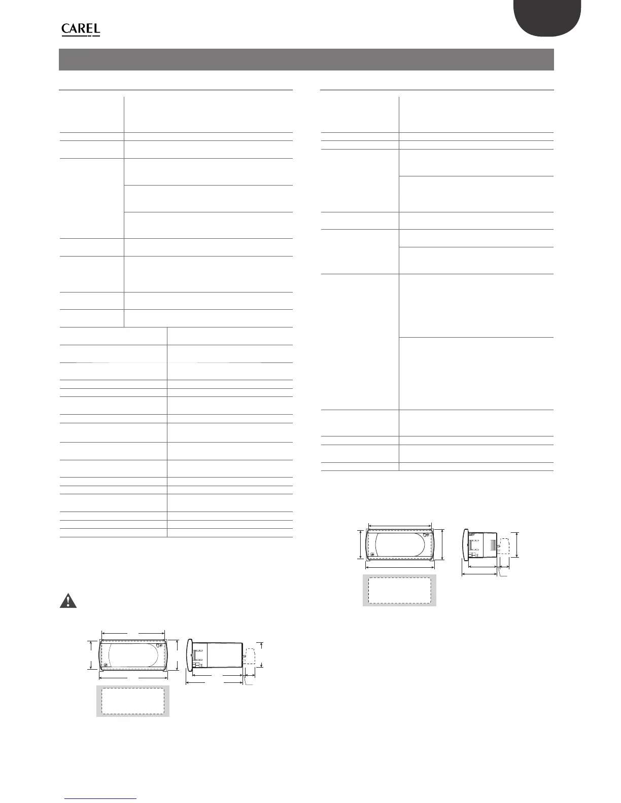
71x29
10
3
33
74
81
36
58
65,29
28.5
Fig. 6.a
6.2 easy compact technical speci cations
power supply (*) 230 Vac, -10+15 % 50/60 Hz;
115 Vac, -10+15 % 50/60 Hz;
12 Vdc ±10% or 12 Vac, ±10% 50/60 Hz (PJEZM*
only, without AUX relay);
rated power 0.5 VA
inputs (*) NTC or PTC probes, 1 or 2 inputs
relay output (*) 2HP relay:
UL: 12A 10 FLA 60 LRA 250 Vac 30000 cycles;
EN60730-1: 10(10)A 250Vac 100000 cycles (**);
16A relay
UL: 12A resistive 5FLA, 30LRA 250Vac 30000 cyc.
EN60730-1: 12(2)A or 10(4)A (N.O. only) 250VAC
100000 cycles;
Type of probe (*) Std CAREL NTC 10 K at 25 °C
Std CAREL PTC 985 at 25 °C
Power supply/relay
output connector (*)
screw terminals, 5 mm pitch for cables with cross-
sect. from 0.5 mm
2
to 1.5 mm
2
; 12A max;
plug-in terminals, 5.08 mm pitch for screw blocks
or with crimped contacts for cables with cross-
sect. from 0.5 mm
2
up to 2.5 mm
2
; 12A max;
Probe connector (*) screw terminals:
- 2 pin, 5 mm pitch for models with 1 probe
(cable cross-section from 0.5 mm
2
to 1.5 mm
2
);
12A max;
- 3 pin, 3.81 mm pitch for models with 2 probes
(cable cross-section from 0.08 mm
2
to 1.5 mm
2
);
6A max;
plug-in terminals for screw blocks or with
crimped contact:-
2 pin, 5.08 mm pitch for models with 1 probe
(cable cross-section from 0.5 mm
2
to 1.5 mm
2
);
12A max;
- 3 pin, 3.81 mm pitch for models with 2 probes
(cable cross-section from 0.08 mm
2
to 1.5 mm
2
);
8 A max;
Serial connector 1 connector for the network of supervisor
connection or for the parameter programming
key (only on the models where featured);
Assembly using screws from the front or with rear brackets
Display LED display, 2 digits plus sign, decimal point and
compressor icon
Keypad 3 membrane buttons
Table 6.b
(*) The features shown depend on the model.
(**) Minimum T OFF between two starts must be greater than 1 min.
71x29
36
81
74
33
38,29
31
28.5
10
3
Fig. 6.b
 Loading...