9
GB
easy way ARIA +030220841 - rel. 1.0 - 26.10.2007
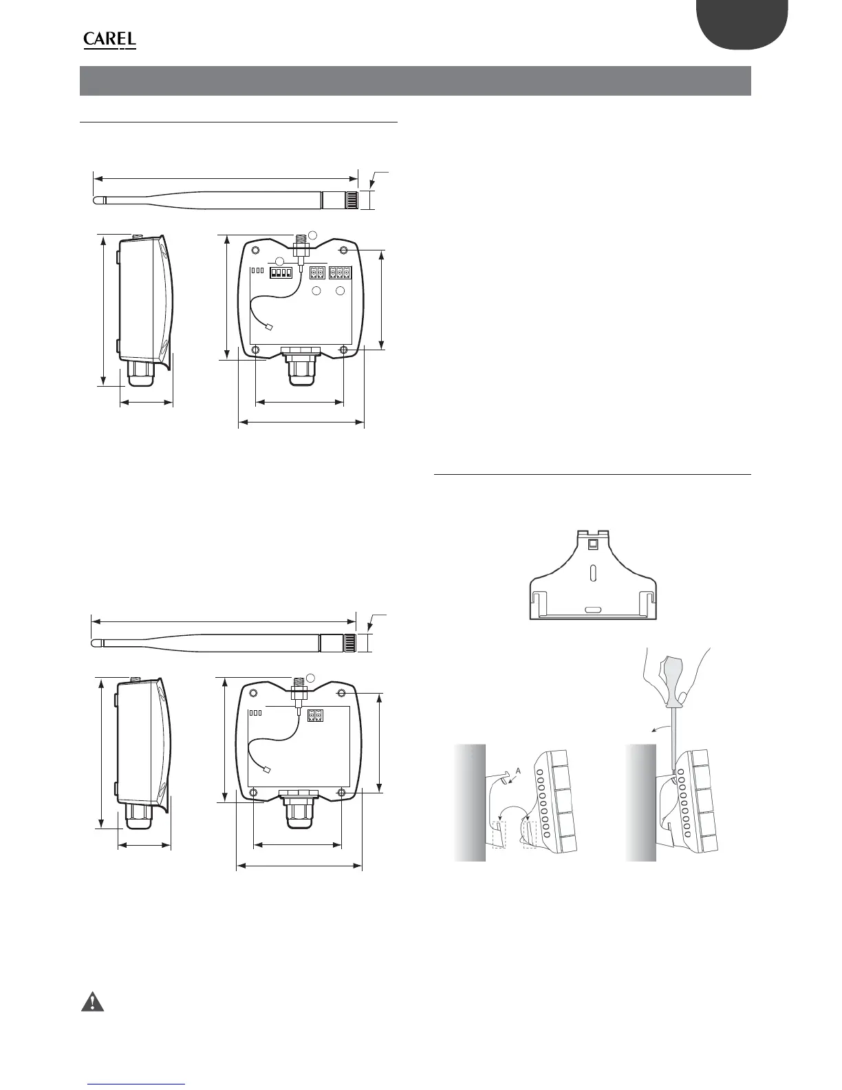
2.1 Access point and Repeater
Access Point
94
102
40
108
196
50
13
DI P: 1 2 3 4
++
G
--
12
3
4
Rx- Rx+ GND
L1
L2 L3
70
Fig. 2.a
Fasten the access point/repeater to the wall with the cable gland •
facing downwards;
connect the RS485 network to terminal (4); •
tighten the antenna in the special housing (2), position it vertically to •
the oor;
connect the power supply to terminal (1), ensuring the polarity •
indicated for DC power supply;
Repeater
94
102
40
108
196
13
+-
1
4
L1
L2 L3
50
70
Fig. 2.b
Fasten the repeater to the wall with the cable gland facing •
downwards;
tighten the antenna in the special housing (2), position it vertically to •
the oor;
connect the power supply to terminal (1), ensuring the polarity •
indicated for DC power supply.
Important: If the same power supply is shared by more than one
unit, connect the same wire from the transformer to the “–“
terminal of the power supply (1).
General warnings
Fasten the access point/repeater in the desired position, considering •
that as the device being installed is a radio device, the following simple
rules must be observed:
avoid enclosing the appliance between two metal walls; –
the e ciency of radio transmission is reduced when there are –
obstacles, metal shelving or other objects that may block the
reception of the wireless signals;
if the product is wall-mounted, fasten it to a masonry wall rather –
than a metal wall, to improve the range of the signal;
remember that the best position for the access point is one where it –
is “visible” to the other devices. It should be positioned in such a way
as to minimise any obstacles;
like all radio equipment, avoid installing the access point near other –
electronic appliances, so as to avoid interference.
do not install the instruments in environments with the following •
characteristics:
strong vibrations or knocks; –
exposure to water sprays; –
exposure to direct sunlight or the elements in general; –
If the appliance is used in a way that is not described by the –
manufacturer, the speci ed level of protection may be a ected.
2.2 Terminal and Sensor
The terminal and the sensor can be fastened to the wall using the support
shown in the gure (included with the product).
Fig. 2.c
Fig. 2.d
Part A shown in the gure is used to lock the instrument to the support.
A screwdriver will be required to remove the instrument. This plastic part
may be essential for hotel-type applications. For applications where the
instrument needs to be removed frequently (residential, o ce,…) part A
can be eliminated simply.
2. INSTALLATION

 Loading...