8.5 Descrizione DIFFERENZIALE/LOGICA: C37,
C41, C45, C49
Questo parametro è attivo solo se l’uscita è abilitata per la
regolazione, ovvero DIPENDENZA=1 o 2. DIFFERENZIA-
LE/ LOGICA si identifica con C37 per l’OUT 1, C41 per
l’OUT 2, C45 per l’OUT 3 e C49 per l’OUT 4. Esso per-
mette di definire l’isteresi dell’uscita ovvero, nel caso di
funzionamento ON/OFF, il punto di spegnimento dell’usci-
ta o, nel caso di funzionamento PWM, il punto in cui l’usci-
ta assume il valore minimo (tempo di ON=0):
DIFFERENZIALE/LOGICA con il parametro precedente,
INSERZIONE identifica la banda proporzionale di regola-
zione. Il parametro DIFFERENZIALE/LOGICA è espresso
in valore percentuale, varia da -100 a +100 del differenzia-
le di lavoro e, cosa importante da ricordare, è legato al
punto di ‘attacco’ definito da INSERZIONE (si ricorda che
INSERZIONE invece è legato al set). Il suo valore è il
reale valore in percentuale del differenziale dell’uscita in
esame. Va da sè che:
- se l’uscita è riferita a St1 (DIPENDENZA= 1)
DIFFERENZIALE /LOGICA è relativo al valore di P1; se
l’uscita è riferita a St2 (DIPENDENZA= 2)
DIFFERENZIALE/LOGICA è relativo al valore di P2.
- con DIFFERENZIALE/LOGICA positivo il punto di
disattivazione è superiore al punto di attacco e si crea
una logica di tipo Reverse. Viceversa, con
DIFFERENZIALE/ LOGICA negativo, il punto di
disattivazione è a livello inferiore del punto di attacco,
si crea una logica di tipo Direct.
Nota: come per il parametro INSERZIONE, anche per
DIFFERENZIALE/LOGICA la scelta di un valore percen-
tuale è stata dettata dall’esigenza di poter creare la logica
della regolazione. L’utente per modificare i punti di attacco
e di stacco non dovrà intervenire direttamente su questi
parametri ma sul set-point e/o differenziale.
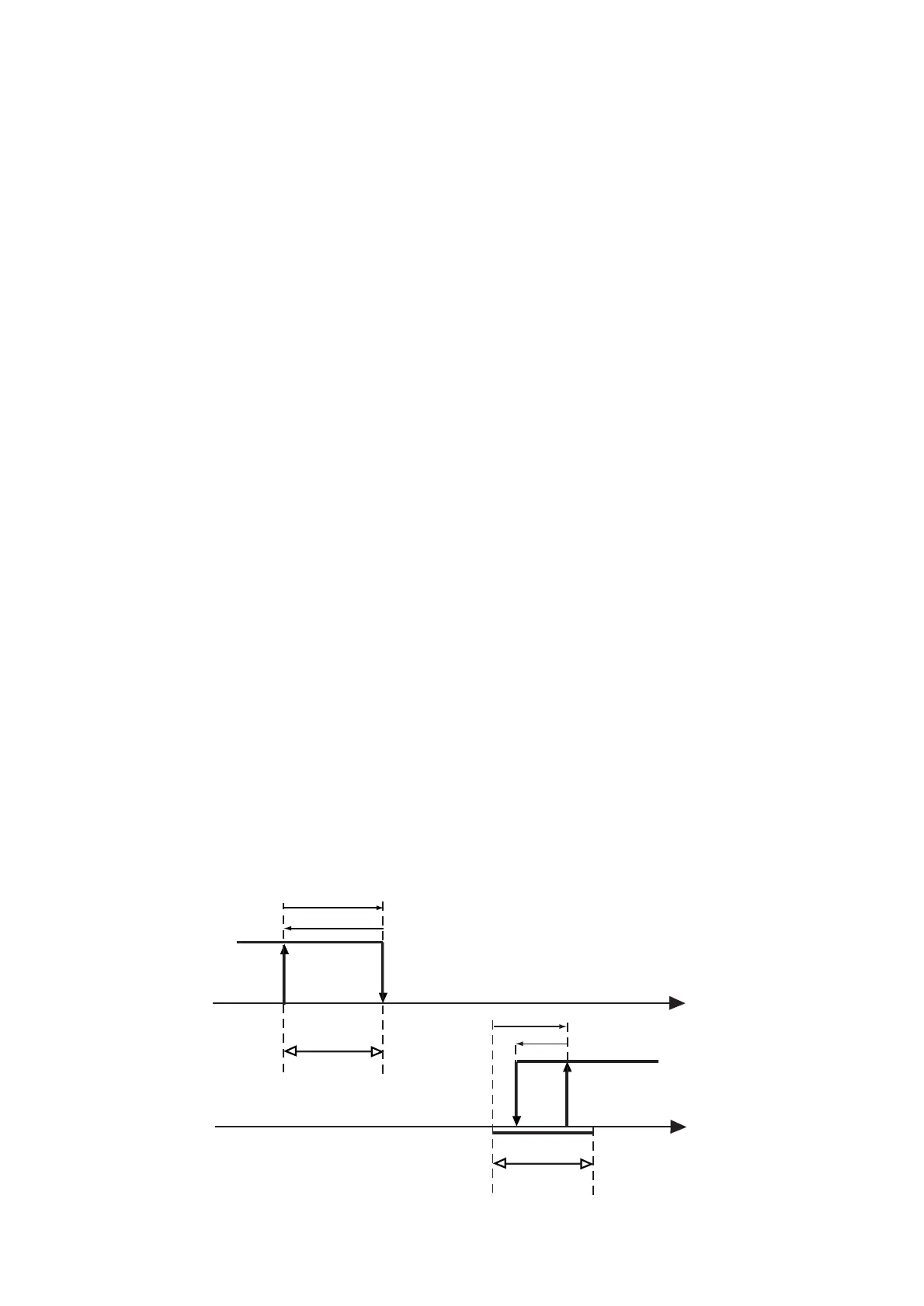
Esempio 9:
Nel disegno viene completato l’esempio 7 aggiungendo i
punti di disattivazione A’ e B’. Per la prima uscita si richie-
de un funzionamento Reverse e il differenziale pari a P1;
per la seconda una logica Direct e il differenziale pari a
metà P2.
8.5 DIFFERENTIAL/LOGIC: C37, C41, C45, C49
This parameter operates only with control outputs, that is
when DEPENDENCE=1 or 2. DIFFERENTIAL/LOGIC
corresponds to C37 for OUT1, C41 for OUT2, C45 for
OUT3 and C49 for OUT4. DIFFERENTIAL/LOGIC
determines the hysteresis of the output, that is, in
ON/OFF logic, the disenergisation point of the output, and,
in PWM logic, the minimum value of the output (ON
time=0):DIFFERENTIAL/LOGIC, as well as ENERGIZATION,
identifies the proportional control zone. Differential/Logic is
a percentage ranging from -100 to +100 of the operating
differential and it is linked to the energization point
defined by ENERGIZATION (ENERGIZATION is linked to
the set-point). Its value corresponds to the real value
(in percentage) of the relevant output differential.
So:
- If the output is related to St1 (DEPENDENCE=1),
DIFFERENTIAL/LOGIC depends on P1; if the output
is related to St2 (DEPENDENCE=2),
- DIFFERENTIAL/LOGIC depends on P2. When
Differential/logic is given a positive value, the
disenergization point is higher than the activation point
(REVERSE logic). Viceversa, when Differential/Logic is
a negative value, the disenergization point is lower than
the activation point (DIRECT logic).
Important: as for ENERGIZATION, DIFFERENTIAL/
LOGIC allows you to define the operating logic (Direct or
Reverse) by giving this parameter a percentage value.
This ensure an easy and straightforward modification of
the energization/disenergization points by simply
modifying set-point and/or differential.
Example no. 9:
The graph below completes example no. 7 above with the
addition of disenergization points A' and B'. The first out-
put operates in the Reverse mode with differential=P1.
The second output operates in the Direct mode with diffe-
rential=P2.
 Loading...