12
NOTE: During this operation, maintain water circulation
through the chiller cooler and condenser vessels to prevent
tube freeze-up.
DISTILLING THE REFRIGERANT — Refrigerant vapor is
transferred from the chiller cooler vessel or pumpout storage
tank through the pumpout condenser, condensed to a liquid,
and pumped to the chiller condenser vessel. During this opera-
tion, water circulation must be maintained in the pump-out
condenser. Refrigerant impurities left in the chiller cooler ves-
sel or storage tank are then drained off. This operation can take
from 4 to 14 hours, depending on the type and amount of re-
frigerant being distilled.
The Pumpout and Refrigerant Transfer Procedures section
gives step-by-step instructions on performing these operations.
Pumpout and Refrigerant Transfer Proce-
dures —
Three possibilities are available:
1. If there are no isolation valves on the chiller, a complete
pumpout system with a pumpout storage tank and pump-
out unit is needed.
2. Whether or not isolation valves are available on the chill-
er, the refrigerant can be pumped to and isolated in a
pump-out storage tank by using the pumpout unit.
3. If isolation valves are available on the chiller, the refriger-
ant can be pumped to either the cooler vessel or the con-
denser vessel using the pumpout unit.
NOTE: Oil should be visible in the pumpout compressor sight
glass under all operating conditions and during shutdown. If oil
is low, add oil as described in the Maintenance section.
The following procedures describe how to transfer refriger-
ant from one vessel to another and how to evacuate the chiller.
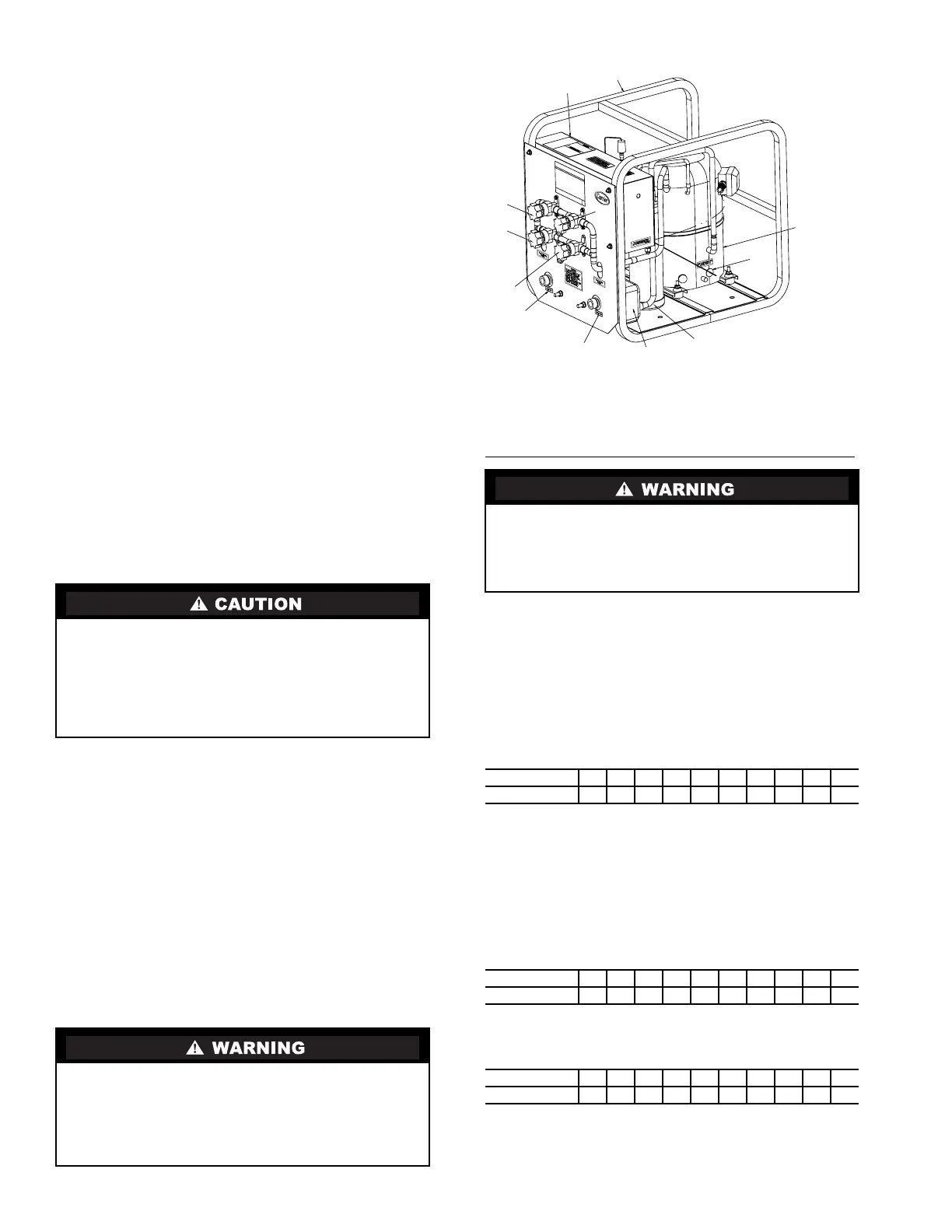
OPERATING THE PUMPOUT UNIT — Connect all refrig-
erant lines to pumpout as shown in Fig. 6.
TO READ REFRIGERANT PRESSURES — During pump-
out or leak testing:
1. Refer to the display on the chiller control center to deter-
mine refrigerant-side pressures and low (soft) vacuum.
Use a quality vacuum indicator or manometer to measure
evacuation and dehydration and to ensure the desired
range and accuracy.
2. Attach a 30 in. Hg vacuum -0-400 psi (101-0-2760 kPa)
compound gage to the storage tank to determine its
pressure.
POSITIVE PRESSURE CHILLERS WITH STORAGE
TANKS — In the Valve/Condition tables that accompany
these instructions, the letter “C” indicates a closed valve.
Figures 9 and 10 show the locations of the valves.
Transfer Refrigerant from Pumpout Storage Tank to Chiller
1. Equalize refrigerant pressure.
a. Turn on chiller water pumps and monitor chiller
pressures.
b. Close pumpout and storage tank valves 2, 4, 5, and
10, and close refrigerant charging valve 7; open
chiller isolation valve 11 and any other chiller iso-
lation valves, if present.
c. Open pumpout and storage tank valves 3 and 6;
open chiller valves 1a and 1b.
d. Gradually crack open valve 5 to increase chiller
pressure to 35 psig (241 kPa). Slowly feed refriger-
ant to prevent freeze-up.
e. Open valve 5 fully after the chiller pressure rises
above the freezing point of the refrigerant. Let the
storage tank and chiller pressure equalize. Open
refrigerant charging valve 7 and storage tank
charging valve 10 to let liquid refrigerant drain into
the chiller.
2. Transfer remaining refrigerant.
a. Close valve 5 and open valve 4.
Do not mix refrigerants from chillers that use different
compressor oils. Compressor damage can result. The
pumpout oil separator comes pre-charged with 13 oz of
ISO viscosity 220 POE (Polyol Ester) oil. The pumpout
compressor is approved for use with ISO viscosity 220
POE oil or ISO viscosity 68 POE oil. The pumpout com-
pressor is also factory precharged with oil.
Always run chiller cooler and condenser water pumps and
always charge or transfer refrigerant as a gas when chiller
vessel pressure is less than 35 psig (241 kPa). Below these
pressures, liquid refrigerant flashes into gas, resulting in
extremely low temperatures in the cooler/condenser tubes
and possibly causing tube freeze-up.
During transfer of refrigerant into and out of the 19XR
storage tank, carefully monitor the storage tank level gage.
Do not fill the tank more than 90% of capacity to allow for
refrigerant expansion. Overfilling may result in damage to
the tank and personal injury.
VALVE 1a1b2345671011
CONDITION C C C C C
VALVE 1a1b2345671011
CONDITION C C
VALVE 1a1b2345671011
CONDITION C C
COMPRESSOR
OIL
SEPARATOR
CONDENSER
LEAVING
WATER
ENTERING
WATER
VALVE
5
VALVE
4
VALVE
2
CONTROL
PANEL
FRAME
ASSEMBLY
OIL
HEATER
VALVE
3
Fig. 9 — Pumpout Unit
 Loading...